Pen needle and safety shield system

a pen needle and safety shield technology, applied in the field of improved pen needles and safety shield systems, can solve the problems of inconvenient manipulation of standard prior art hypodermic syringes, potential needle sticks, and complicated track systems that may not always be reliable, so as to eliminate rotational movement of shields or complex track systems, the effect of reducing the risk of needle sticking

Inactive Publication Date: 2007-12-20
BECTON DICKINSON & CO
View PDF15 Cites 44 Cited by
  • Summary
  • Abstract
  • Description
  • Claims
  • Application Information

AI Technical Summary

Benefits of technology

[0011] At least one of the channel-shaped tracks in the shield includes an opening spaced from but near the open end of the shield, and means is provided to prevent the free end of the resilient finger from being received in the opening during retraction of the shield from the first position enclosing the second end of the needle cannula to expose the needle cannula as described. Thus, the shield may be retracted to expose the second end of the needle cannula during injection, but the resilient finger will lock into the opening when the spring extends the shield to enclose the second end of the needle cannula following injection. The shield is thereby locked in the first position enclosing the second end of the needle cannula following injection. In the preferred embodiment, wherein the free end of the resilient fingers are hook-shaped as described above, the hook-shaped portion of the finger is received through the opening and securely locks the shield in the closed position. In the most preferred embodiment, each of the channel-shaped tracks include an opening which receives and secures each of the locking fingers. The improved safety shield system of this invention thus permits one retraction of the safety shield during injection and locks the safety shield to enclose the second end of the needle cannula following injection. Although various means may be utilized to prevent receipt of the locking fingers in the openings in the channel-shaped tracks during retraction of the safety shield to expose the needle cannula, a preferred embodiment includes a resilient detent or finger portion in the tracks adjacent the opening which resiliently biases the fingers of the clip member inwardly, such that the resilient fingers of the clip member travel past the opening during retraction of the shield member to the second position as described above. Further, the resilient detents catch the hook-shaped end portions of the resilient fingers during extension of the shield, assuring locking of the shield in the extended position following injection.
[0012] The preferred embodiment of the safety shield system of this invention further includes a removable cup-shaped cap which is received over the shield prior to use. As will be understood, the cap is then removed and the pen injector is ready for use as described above. However, the cap of the improved safety shield system of this invention may also be used to safely store and dispose of the double ended needle cannula. As described above, the second end of the needle cannula is protected following injection by the safety shield which is locked in the extended position surrounding the second end of the needle cannula. The needle cannula and safety shield system may then be safely stored in the cap for disposal by removing the needle cannula and safety shield assembly from the pen injector and inserting the first end of the needle cannula into the cup-shaped cap which is configured and adapted to receive and store the assembly for safe disposal. That is, the first end of the needle cannula is then located in the cup-shaped cap preventing exposure to the needle cannula and the second end portion is safely enclosed by the safety shield which is locked in the extended position protecting the second end of the needle cannula.
[0013] The safety shield system of this invention thus provides reliable operation and protection from the needle cannula. In the preferred embodiment, the generally tubular safety shield moves axially guided by the axially extending channel-shaped tracks as described above, thereby eliminating rotational movement of the shield or a complex track system. In the most preferred embodiment, the tubular body portion of the clip member includes a plurality of spaced axially extending radially projecting ribs which are received in axially extending grooves in the tubular portions of the shield, assuring axial movement of the shield during retraction and extension of the shield as described above. In the most preferred embodiment, the resilient fingers of the clip member include a U-shaped portion integrally connected to the tubular portion of the clip member and hook-shaped free end portions as described above. This configuration provides additional resiliency for the hook-shaped end portions of the fingers. Further, the U-shaped portion of the fingers preferably open toward the generally closed end of the shield and the spring includes a first end received in the U-shaped portions of the fingers and a second end biased against the generally closed end of the shield assuring reliable movement of the shield.
[0014] The pen needle and safety shield system of this invention also prevents retraction of the shield during assembly of the safety shield system on the pen injector. As set forth above, one problem with the prior art pen needles has been potential piercing of the cap during threaded assembly of the cap and shield assembly on the pen dispenser thereby exposing the user to puncture. The cap of the improved safety shield system includes a plurality of radially inwardly projecting ribs which are received in the axially extending grooves in the tubular portion of the shield against the axially projecting ribs on the clip member. The grooves in the tubular portion of the shield preferably extend through the side wall of the shield from adjacent the generally closed end to the ribs. These internal ribs on the cap prevent retraction of the shield during threaded assembly of the cap and shield assembly on the pen injector, thereby preventing accidental puncture during assembly.

Problems solved by technology

The required manipulation of a standard prior art hypodermic syringe can be inconvenient, particularly where the injection is self-administered in a public environment.
However, such complicated track systems may not always be reliable.
One problem with other pen needle accessories, such as hidden needle adapters, has been potential needle sticks to the user during assembly of the accessory on the pen injector.
This may cause the needle to pierce the cap and possibly puncture the user during assembly.
Another problem associated with pen needles has been the safe disposal of the hub and double ended needle cannula.

Method used


Image

  • Pen needle and safety shield system
  • Pen needle and safety shield system
  • Pen needle and safety shield system

Examples


Embodiment Construction

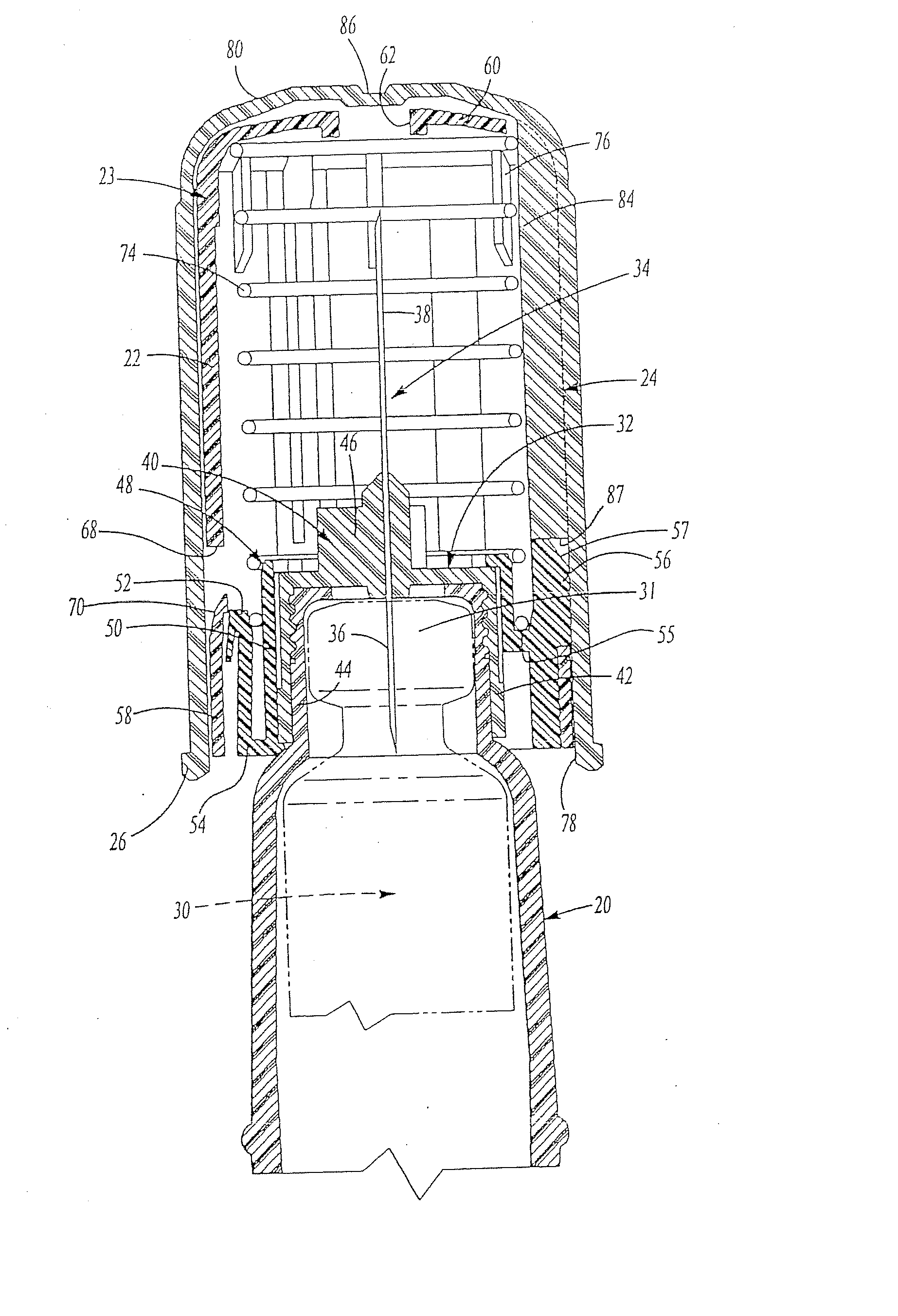
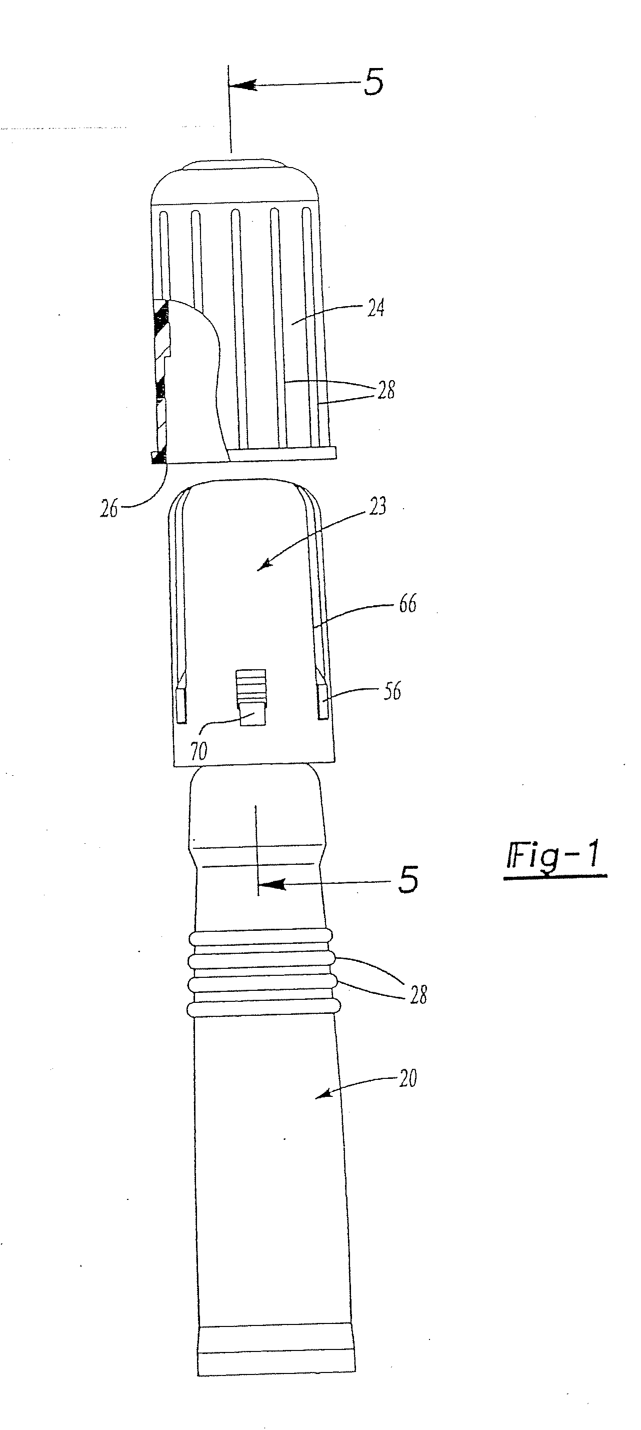
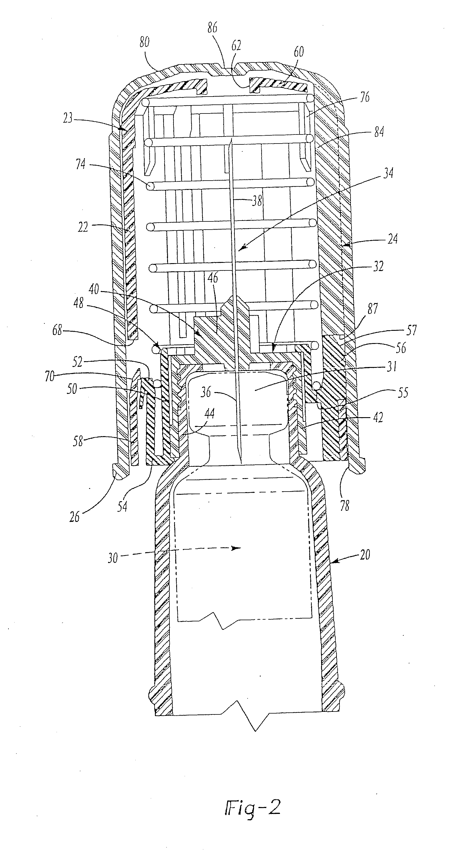
[0024] As set forth above, the improved safety shield system of this invention is particularly but not exclusively adapted for pen injectors, such as the pen needles available from Becton Dickinson & Company best shown at 20 in FIGS. 1 and 2. As will be understood, however, the safety shield system of this invention may also be used with other pen injectors of this general type and with conventional hypodermic syringes as described above.

[0025] As described below, the safety shield 22 normally encloses the second end 38 of the needle cannula 34 as shown in FIG. 2 and the safety shield assembly 23 is enclosed by a cup-shaped cap 24 as shown in FIG. 1. The disclosed embodiment of the pen needle 20 includes an open end 26 which may include external ribs 28 to facilitate gripping of the pen needle 20 by the user for threaded attachment of the assembly to the pen injector as described below. As shown in FIG. 2, the pen injector 20 receives a vial shown in phantom at 30 having a pierceab...


PUM


Abstract

A safety shield system for a needle cannula of a pen needle injector or similar device, wherein the safety shield may be retracted from a first position enclosing the needle to a second position exposing the needle for injection. The safety shield system permits retraction of the safety shield during use, but extends the shield enclosing the needle in a locked position following use. The shield system is utilized with a pen needle injector having a double ended needle cannula mounted in a hub received on the open end of the pen needle injector. The assembly is disposed of by removing the assembly and needle cannula hub and storing the assembly in the cup-shaped cap enclosing the exposed end of the needle cannula within the cap. The cap includes internal radial ribs preventing retraction of the shield prior to removing the cap preventing inadvertently piercing the cap during assembly.

Description

CROSS-REFERENCE TO RELATED APPLICATIONS [0001] This application claims priority to PCT Application No. PCT / US01 / 23367 filed Jul. 25, 2001, which claims priority to U.S. Provisional Application No. 60 / 222,454 filed Aug. 2, 2000. FIELD AND BACKGROUND OF THE INVENTION [0002] The present invention relates to an improved pen needle and safety shield system particularly, but not exclusively, adapted for pen injectors. The safety shield system of this invention includes a retractable generally tubular shield which is spring biased to normally enclose the needle cannula of a pen needle dispenser, but which locks in the extended position enclosing the needle cannula following injection. Further, the double ended needle cannula assembly may be safely nested in the cup-shaped cap following injection for disposal. [0003] Hypodermic syringes have been used for many years to deliver selected doses of fluids including liquid medicaments, inoculations, etc. to patients. However, many applications u...

Claims


Application Information

Patent Timeline
Patent Type & Authority Applications(United States)
IPC IPC(8): A61M5/00A61D7/00A61M5/24A61M5/31A61M5/32A61M5/34
CPCA61D7/00A61M5/24A61M5/3202A61M5/3205A61M5/326A61M2205/6081A61M5/347A61M2005/3104A61M2005/3247A61M2005/3267A61M2205/583A61M5/3271
Inventor GIAMBATTISTA, LUCIODESALVO, DAVID E.
Owner BECTON DICKINSON & CO
Why Eureka
Try Eureka