Eureka AIR delivers breakthrough ideas for toughest innovation challenges, trusted by R&D personnel around the world.

Dynamic shielding system of cellular signals for an antenna of an unmanned aerial vehicle

a technology of dynamic shielding and cellular signals, which is applied in the direction of wireless communication, assessment restriction, transportation and packaging, etc., can solve the problems of network coverage, signal interference and/or loss, and other ground level occurrences, and achieve the effect of avoiding interference and/or loss

Active Publication Date: 2018-10-11
AT&T INTPROP I L P
View PDF2 Cites 32 Cited by
  • Summary
  • Abstract
  • Description
  • Claims
  • Application Information

AI Technical Summary

Benefits of technology

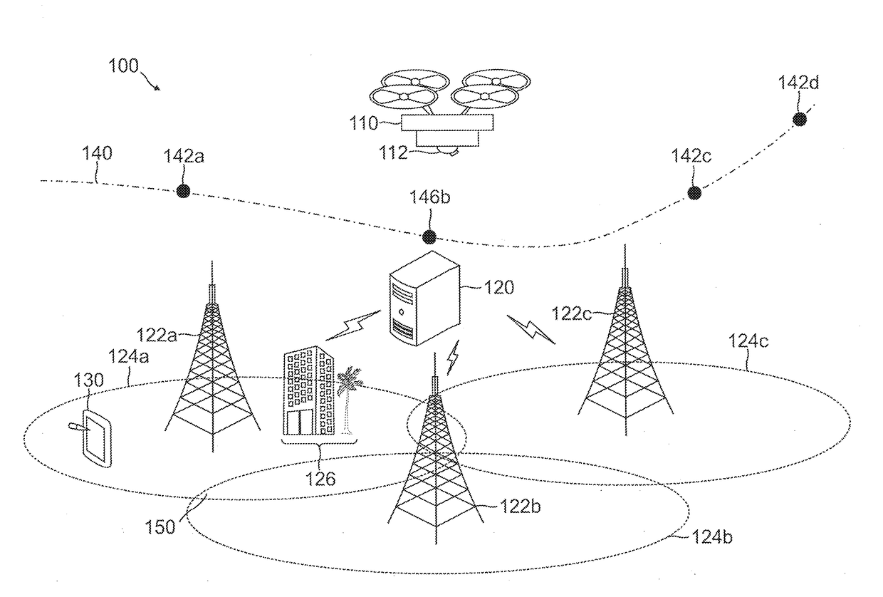
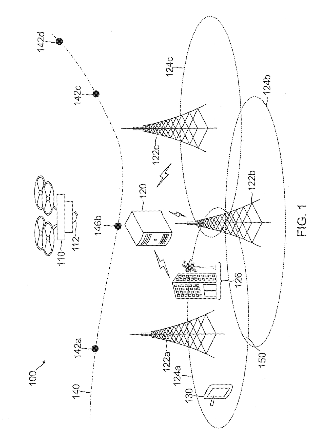
The patent describes a method to provide network connectivity to an antenna on a drone operating at high altitude. The antenna is shielded using RF signal absorbing material to prevent interference from the surrounding environment. The shield can be adjusted based on the drone's location to connect with different base stations and prevent signal loss. This technology allows for seamless network connectivity for drones operating at high altitude.

Problems solved by technology

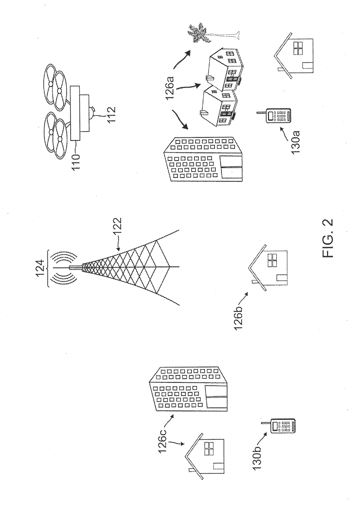
In such cases, ground level objects (e.g., buildings and other manmade objects, trees and other natural obstacles, etc.) and geographic conditions (e.g., landforms including hills, mountains, etc. that may affect signal transmissions) may cause signal interference, reception problems, and issues in network coverage.
In other embodiments, signal interference and / or loss may occur from other ground level occurrences, including loss due to bodies (e.g., people) and in-vehicle loss from transportation vehicles utilized by people during use of UEs.
However, UAVs travelling at altitude may instead encounter little to no ground level interference from ground level factors and / or may encounter different signal interferences on the cellular network, such as multiple base station signals interfering at altitude.

Method used


Image

  • Dynamic shielding system of cellular signals for an antenna of an unmanned aerial vehicle
  • Dynamic shielding system of cellular signals for an antenna of an unmanned aerial vehicle
  • Dynamic shielding system of cellular signals for an antenna of an unmanned aerial vehicle

Examples


Embodiment Construction

[0019]The detailed description set forth below is intended as a description of various configurations of the subject technology and is not intended to represent the only configurations in which the subject technology can be practiced. The appended drawings are incorporated herein and constitute a part of the detailed description. The detailed description includes specific details for the purpose of providing a thorough understanding of the subject technology. However, it will be clear and apparent to those skilled in the art that the subject technology is not limited to the specific details set forth herein and may be practiced using one or more embodiments. In one or more instances, structures and components are shown in block diagram form in order to avoid obscuring the concepts of the subject technology. One or more embodiments of the subject disclosure are illustrated by and / or described in connection with one or more figures and are set forth in the claims.

[0020]Various techniq...


PUM


Abstract

Example methods, apparatus, systems, and machine-readable mediums for a dynamic shield system of cellular signals for an antenna of an unmanned aerial vehicle are disclosed. An example method may include receiving a navigation route for an unmanned aerial vehicle to execute during flight of the unmanned aerial vehicle and determining an orientation of a radio signal shield for an antenna of the unmanned aerial vehicle using ground level signal propagation information of radio signals for a network and the navigation route, wherein the radio signal shield prevents the radio signals from being received by the antenna from directions based on the orientation. The method may further include adjusting the radio signal shield using the orientation and communicating with a cellular base station of the network using the antenna.

Description

FIELD OF THE DISCLOSURE[0001]This disclosure relates generally to wireless communication networks and drone device usage and, more particularly, to a dynamic shield system of cellular signals for an antenna of an unmanned aerial vehicle.BACKGROUND[0002]Unmanned aerial vehicles (UAVs), also referred to as unmanned aerial systems (UASs) or more commonly, drones, may be mobile platforms capable of detecting information, delivering goods, handling objects, and / or performing other actions. UAVs may provide many benefits over manned vehicles, including lower operating costs, fewer dangers of usage and / or travel, and increased accessibility to areas that may be dangerous for normal human travel. Moreover, UAVs may perform certain actions without the need for human assistance, for example, through preprogrammed instructions that may free operators to perform other tasks. Thus, UAVs may be preprogrammed to fly a flight path or route that may be navigated by the UAV using one or more flight c...

Claims


Application Information

Patent Timeline
Patent Type & Authority Applications(United States)
IPC IPC(8): H04B7/185H04L29/08G01C21/20B64C39/02
CPCH04B7/18506H04L67/12G01C21/20B64C2201/146H04W84/042H04W84/06H04W88/08B64C39/024H04W4/026H01Q1/28H01Q1/526H04W48/20B64U50/31B64U2201/20B64U2101/64B64U2101/20
Inventor KOSSEIFI, MARIOTHOMAS, JOSEPHDE ROSA, GIUSEPPE
Owner AT&T INTPROP I L P
Why Eureka
Eureka Blog
Learn More