Optical pickup

a pickup and optical technology, applied in the direction of recording information storage, instrumentation, disposition/mounting of the head, etc., can solve the problem of reducing the thickness deviation, and achieve the effect of improving the deterioration of the tracking error signal

Active Publication Date: 2005-07-28
SAMSUNG ELECTRONICS CO LTD
View PDF2 Cites 36 Cited by
  • Summary
  • Abstract
  • Description
  • Claims
  • Application Information

AI Technical Summary

Benefits of technology

[0032] The present invention provides an optical pickup that improves deterioration of a tracking error signal caused by an adjacent layer by suppressing inference light reflected from the adjacent layer.

Problems solved by technology

In an optical disc with a reduced thickness of 0.1 mm, one of the biggest problems is reducing a thickness deviation across the disc to less than ±3 μm.

Method used


Image

  • Optical pickup
  • Optical pickup
  • Optical pickup

Examples


Embodiment Construction

[0057] Reference will now be made in detail to the present embodiments of the present invention, examples of which are illustrated in the accompanying drawings, wherein like reference numerals refer to the like elements throughout. The embodiments are described below in order to explain the present invention by referring to the figures.

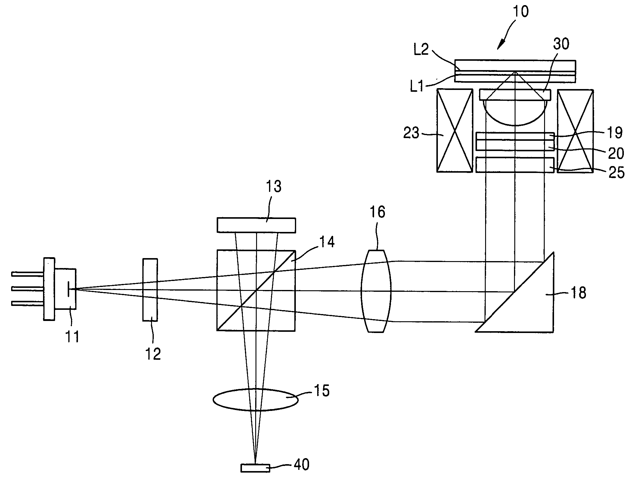
[0058]FIGS. 6 and 7 are views of an optical system of an optical pickup according to an embodiment of the present invention. Referring to FIGS. 6 and 7, the optical pickup includes a light source 11, an objective lens 30, an optical path changer, i.e., the polarization beam splitter 14 shown in FIG. 6, a photodetector 40, and an optical member 25. The objective lens30 focuses light emitted from the light source 11 to be formed into a light spot on a recording medium, i.e., an optical disc 10. The optical path changer changes a propagation path of incident light. The photodetector 40 detects an information signal and / or error signal by receiving the l...


PUM

PropertyMeasurementUnit
wavelengthaaaaaaaaaa

Abstract

An optical pickup including an optical member which inhibits interference light reflected from an adjacent layer from being received by a photodetector when an optical information storage medium includes a plurality of recording layers on at least one side thereof. The optical pickup suppresses a photodetector, especially first and second sub-photodetectors of the photodetector, from receiving the interference light reflected from the adjacent layer.

Description

CROSS-REFERENCE TO RELATED APPLICATIONS [0001] This application claims the priority of Korean Patent Application No. 2004-2749, filed on Jan. 14, 2004, in the Korean Intellectual Property Office, the disclosure of which is incorporated herein in its entirety by reference. BACKGROUND OF THE INVENTION [0002] 1. Field of the Invention [0003] The present invention relates to an optical recording and / or reproduction device, and more particularly, to an optical pickup to prevent deterioration of a tracking error signal caused by an adjacent layer during recording and / or reproduction of data onto / from a multi-layer recording medium that has a plurality of recording layers on one side. [0004] 2. Description of the Related Art [0005] In an optical recording and / or reproducing apparatus which records information on and / or reproduces information from an optical information storage medium, such as an optical disc, by using laser light focused into a light spot by an objective lens, a recording ...

Claims


Application Information

Patent Timeline
Patent Type & Authority Applications(United States)
IPC IPC(8): G11B7/13G11B7/131G11B7/09G11B7/135G11B7/1353G11B7/24
CPCG11B7/0903G11B7/1353G11B7/131A61J13/00A41C3/128A41C3/144
Inventor KIM, TAE-KYUNGAHN, YOUNG-MANCHUNG, CHONG-SAMKIM, SEOK-JUNGHEOR, TAE-YOUN
Owner SAMSUNG ELECTRONICS CO LTD
Why Eureka
Try Eureka