
Stapling device with grasping jaw mechanism

a stapling device and jaw mechanism technology, applied in the field of surgical stapling devices, can solve the problems of limited access to the surgical site, and achieve the effect of preventing the proximal retraction of the actuating sha

Active Publication Date: 2014-12-18
TYCO HEALTHCARE GRP LP
View PDF6 Cites 51 Cited by
  • Summary
  • Abstract
  • Description
  • Claims
  • Application Information

AI Technical Summary

Benefits of technology

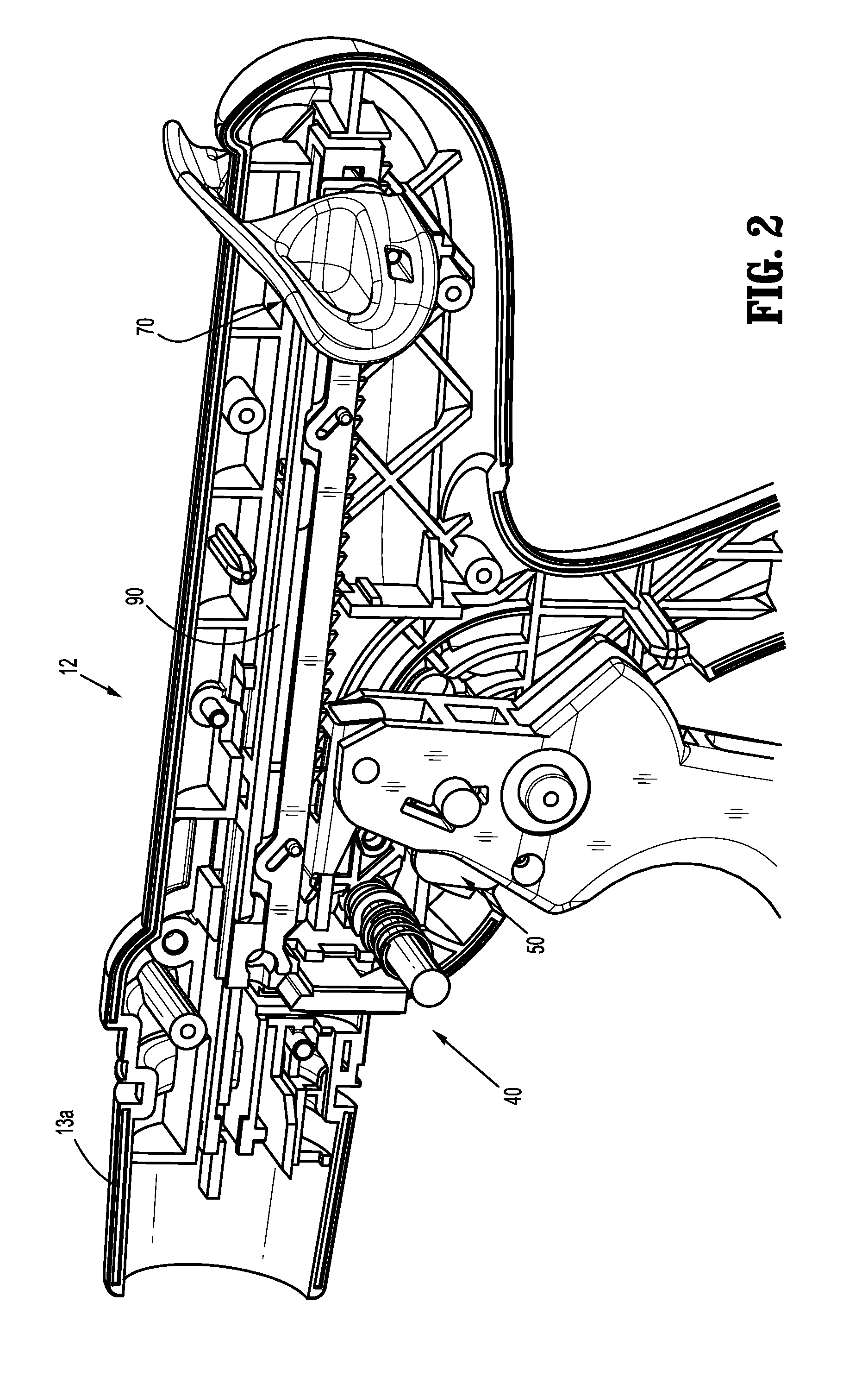
The patent describes a stapling device that can be used in two different modes: a grasping mode and a clamping mode. The device can only be in the grasping mode when the mode selection switch is pressed and the device cannot be easily switched to the clamping mode. This is because a mode pawl prevents the device from transitioning to the grasping mode from the clamping mode. The device can only transition to the grasping mode when the mode selection switch is pressed and the mode pawl is not engaged with the actuation shaft. The technical effect of this feature is that it ensures the device operates in the correct mode and prevents accidental switches during use.

Problems solved by technology

Thus, access to the surgical site is limited.

Method used


Image

  • Stapling device with grasping jaw mechanism
  • Stapling device with grasping jaw mechanism
  • Stapling device with grasping jaw mechanism

Examples


Embodiment Construction

[0051]Embodiments of the presently disclosed grasping jaw mechanism will now be described in detail with reference to the drawings in which like reference numerals designate identical or corresponding elements in each of the several views. As used herein, the term “clinician” refers to a doctor, a nurse, or any other care provider and may include support personnel. Throughout this description, the term “proximal” will refer to the portion of the device closest to the clinician and the term “distal” will refer to the portion of the device furthest from the clinician.

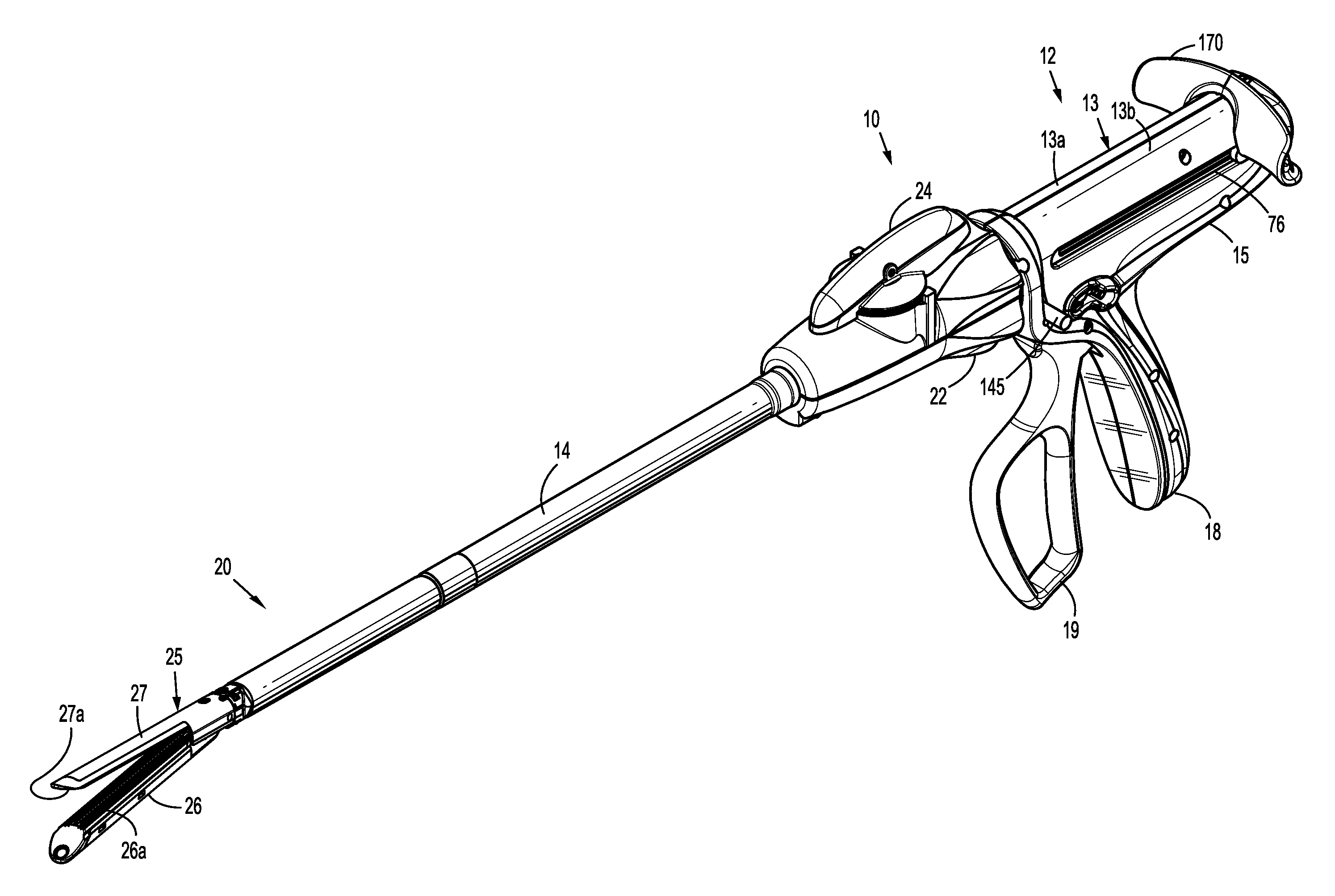
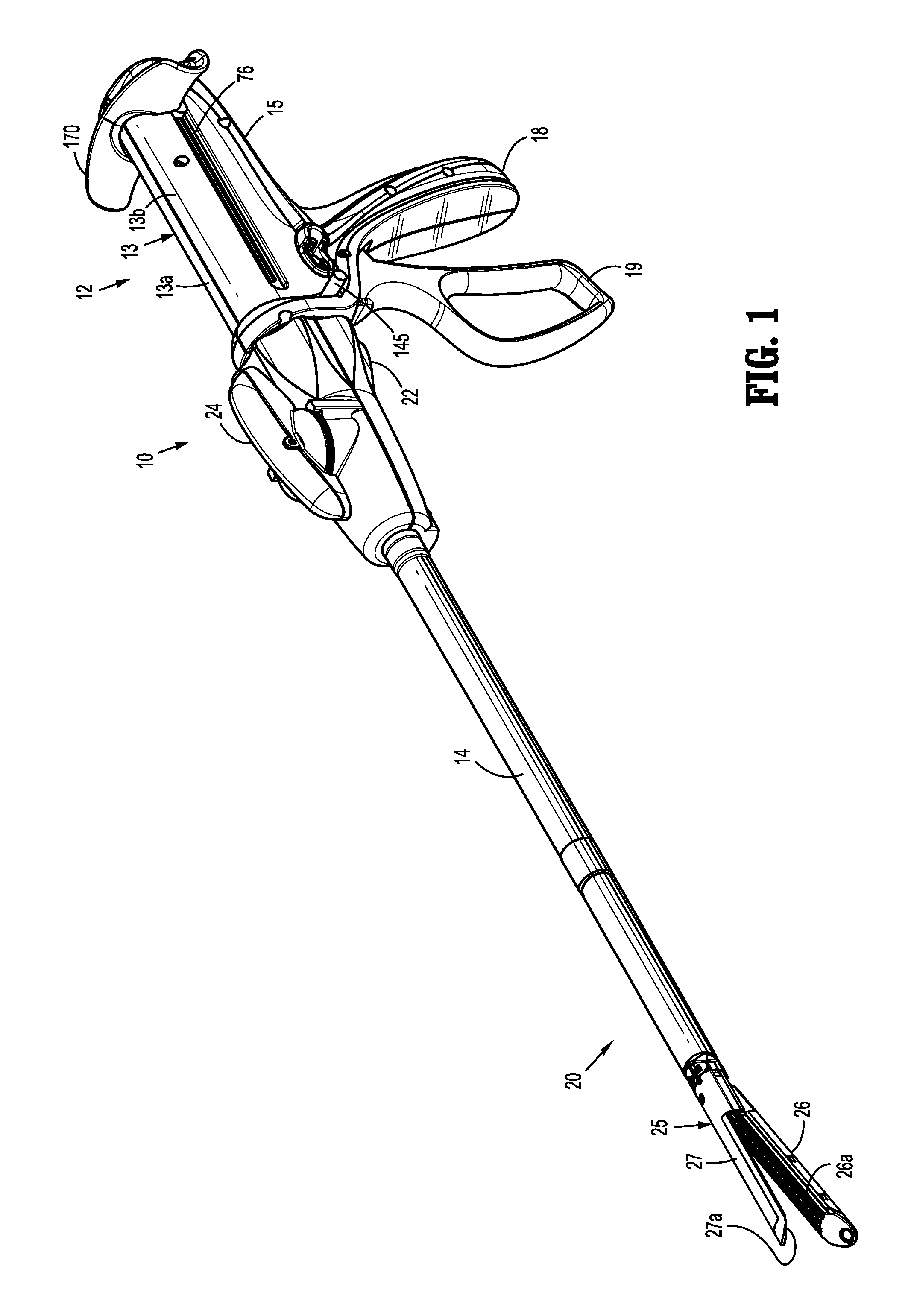
[0052]FIG. 1 illustrates an embodiment of a presently disclosed surgical stapling device 10. Device 10 includes a handle assembly 12, an elongated member 14 extending distally from handle assembly 12 defining a longitudinal axis, and a tool assembly 25 supported on a distal end of the elongated member 14. Tool assembly 25 can be part of a loading unit (“LU”) 20 which is releasably secured to a distal end of elongated memb...


PUM

PropertyMeasurementUnit
Refractionaaaaaaaaaa

Abstract

A surgical device includes a handle assembly, an elongated member, and a tool assembly. The handle assembly includes a mode selection mechanism configured to alternate the surgical device between a grasping mode of operation and a clamping mode of operation. The tool assembly includes a cartridge assembly having a plurality of staples and an anvil assembly. The tool assembly is configured to grasp and release tissue in the grasping mode of operation and configured to clamp and staple tissue in the clamping mode of operation. The mode selection mechanism includes a switch and a pawl. When a moveable handle of the handle assembly is compressed with the switch held in a depressed position, the device is in the grasping mode of operation. When the moveable handle is compressed with the switch in a neutral position, the device is in the clamping mode of operation.

Description

BACKGROUND[0001]1. Technical Field[0002]The present disclosure relates to a surgical stapling device and, more particularly, to a surgical stapling device configured to operate a tool assembly in a grasping mode.[0003]2. Background of Related Art[0004]Surgical devices wherein tissue is first grasped or clamped between opposing jaw structure and then joined by surgical fasteners are well known in the art. The fasteners are typically in the form of surgical staples, but two-part polymeric fasteners can also be utilized.[0005]Such devices can include a tool assembly with a pair of jaws which are used to capture or clamp tissue. Typically, one of the jaws carries a staple cartridge which houses a plurality of staples arranged, for example, in at least two lateral rows while the other jaw supports an anvil that defines a surface for forming the staple legs as the staples are driven from the staple cartridge. The stapling operation may be effected by cam bars that travel longitudinally th...

Claims


Application Information

Patent Timeline
IPC IPC(8): A61B17/068
CPCA61B17/068A61B17/07207A61B17/2909A61B2017/00393A61B2017/2923A61B17/29
Inventor CAPPOLA, KENNETH M.
Owner TYCO HEALTHCARE GRP LP
Learn More