Catheter with sealed hydratable hemostatic occlusion element

Inactive Publication Date: 2013-03-07
CARDIVA MEDICAL
View PDF7 Cites 35 Cited by
  • Summary
  • Abstract
  • Description
  • Claims
  • Application Information

AI Technical Summary

Benefits of technology

[0024]After the hemostatic implant has expanded sufficiently, the occlusion element will be collapsed, and the shaft and collapsed occlusion element withdrawn leaving the hemostatic implant in the tissue tract. As described above, it will usually be preferred to position the hemostatic implant laterally or to the side of the shaft which carries the occlusion element. By thus positioning the occlusion element to bypass the hydrated hemostatic implant, withdrawal of the collapsed occlusion element past the hydrated hemostatic implant can be greatly facilitated. Preferably, the material of the hemostatic implant will degrade over time, preferably over a period of less than one year, more preferably over a period of less than six months, usually less than three months, leaving no material behind at the vascular access point.
[0025]In a preferred aspect of the methods of the present invention, the protective sleeve is latched to the shaft while the shaft is introduced. By “latched” is meant that the sl

Problems solved by technology

The use of the hemostatic implant together with the temporary hemostasis provided by the occlusion element increases the likelihood that even relatively large vascular penetrations can be successfull

Method used


Image

  • Catheter with sealed hydratable hemostatic occlusion element
  • Catheter with sealed hydratable hemostatic occlusion element
  • Catheter with sealed hydratable hemostatic occlusion element

Examples


Embodiment Construction

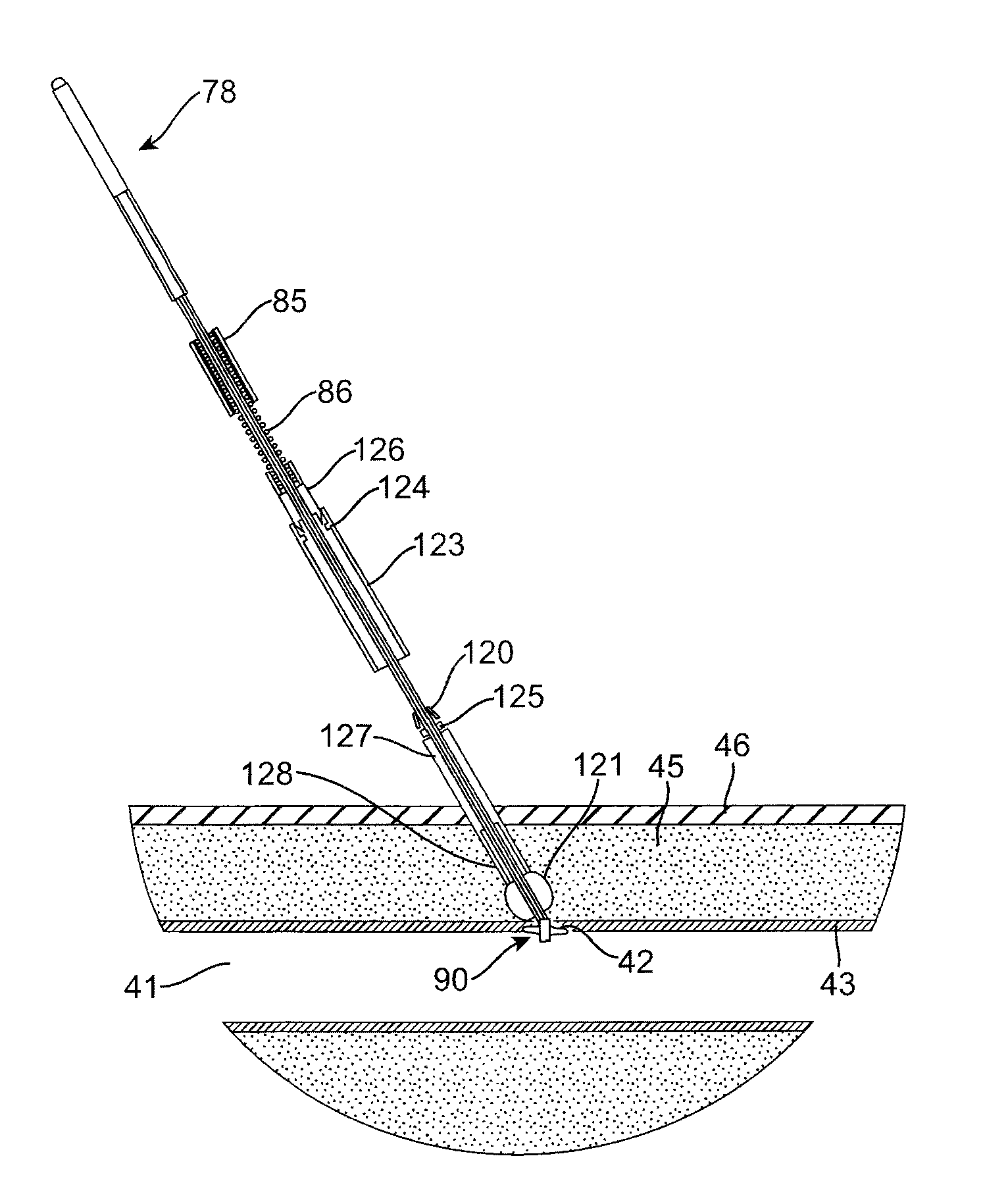
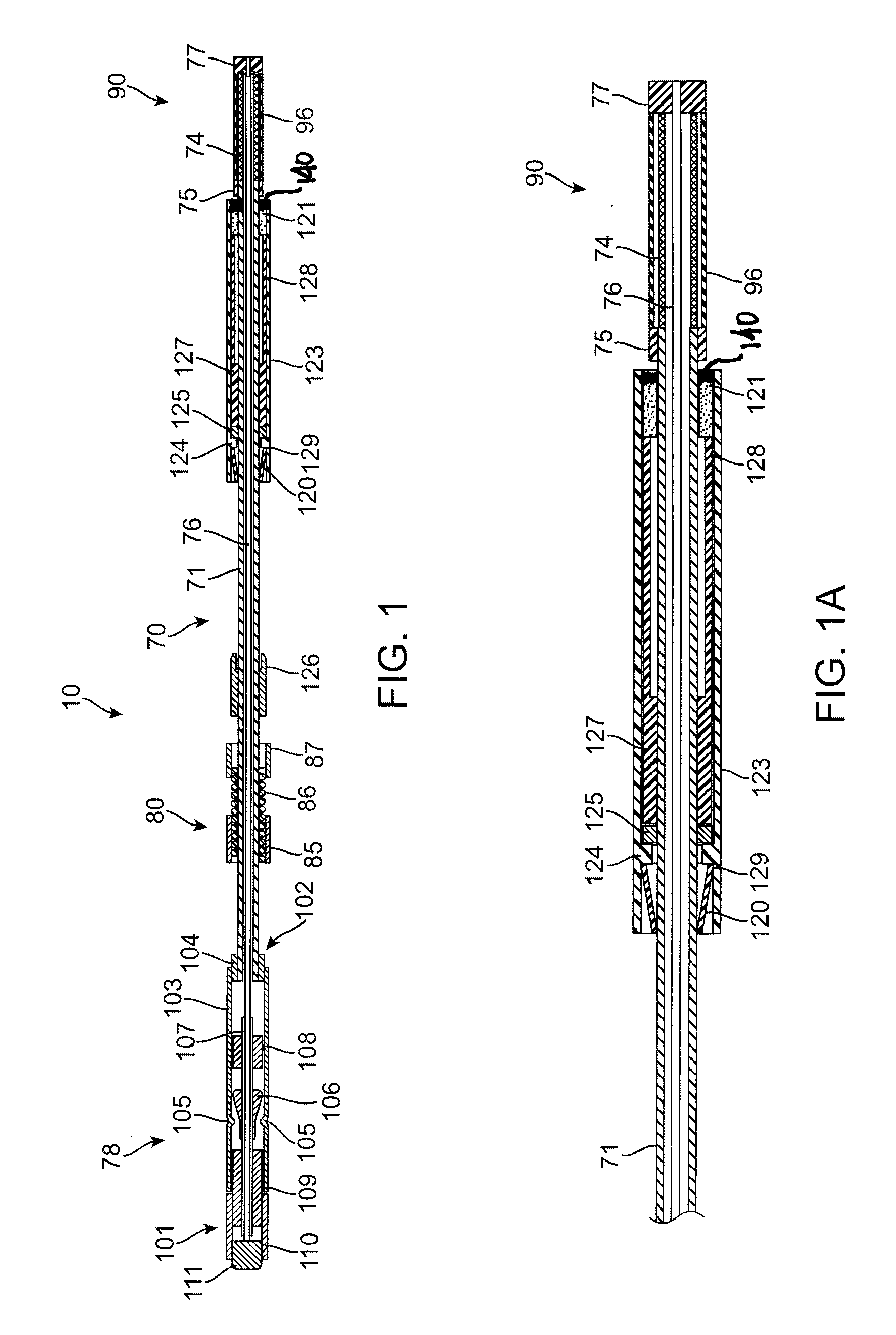
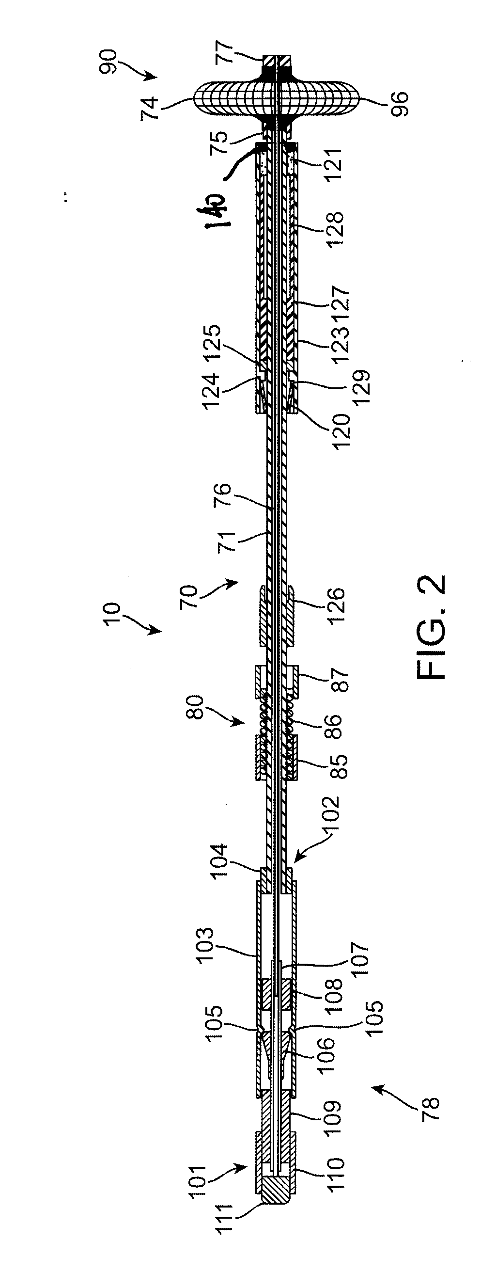
[0040]Referring to FIGS. 1 and 1A, an exemplary sealing apparatus 10 constructed in accordance with the principles of the present invention comprises a shaft assembly 70 including an outer tube 71 and an inner rod 76. An expansible occlusion element 90 is mounted at a distal end (to the right in FIGS. 1 and 1A) of the shaft assembly 70 and includes a radially expansible mesh 74 covered by an elastomeric membrane 96. A handle assembly 78 is attached to a proximal end of the shaft assembly 70 and is operatively attached to both the outer tube 71 and inner rod 76 so that the inner rod can be axially advanced and retracted relative to the outer tube. The inner rod 76 and outer tube 71 are coupled together at the distal tip of the sealing apparatus 10 by a plug 77 and a proximal anchor 75, respectively. The occlusion element 90 is held between the plug 77 and the proximal anchor 75 so that axial retraction of the rod in the proximal direction (to the left as shown in FIGS. 1 and 1A) fore...


PUM


Abstract

Apparatus for sealing a vascular wall penetration disposed at the end of the tissue tract comprises a shaft, an optional occlusion element, a hydratable hemostatic implant, and a protective sleeve. The apparatus is deployed through the tissue tract with the occlusion element optionally occluding the vascular wall penetration and inhibiting backbleeding therethrough. The hydratable hemostatic implant, which will typically be a biodegradable polymer such as collagen carrying an anti-proliferative agent or coagulation promoter, will then be deployed from the sealing apparatus by retracting the protective sleeve and left in place to enhance closure of the vascular wall penetration with minimum scarring. The hydratable implant will be protected from premature hydration and swelling by a soluble plug covering the implant's distal end prior to sleeve retraction.

Description

BACKGROUND OF THE INVENTION[0001]1. Field of the Invention[0002]The present invention relates generally to medical devices and methods. More particularly, the present invention relates to apparatus and protocols for closing arteriotomies and other vascular wall penetrations.[0003]Angiography, angioplasty, atherectomy, and a number of other vascular and cardiovascular procedures are performed intravascularly and require percutaneous access into the patient's vasculature, most often into the arterial vasculature. The most common technique for achieving percutaneous access is called the Seldinger technique, where access to an artery, typically the femoral artery in the groin, is first established using a needle to form a “tract,” i.e., a passage through the tissue overlying the blood vessel. The needle tract is then dilated, and an access sheath is placed into the dilated tract and through a penetration in the vascular wall, such as an arteriotomy to allow the introduction of guidewire...

Claims


Application Information

Patent Timeline
IPC IPC(8): A61B17/03
CPCA61B17/0057A61B2017/00623A61B2017/22067A61B2017/00898A61B2017/00654
Inventor YASSINZADEH, ZIA
Owner CARDIVA MEDICAL
Why Eureka
Try Eureka