Liquid droplet ejection head, apparatus for ejecting liquid droplet, and method of producing liquid droplet ejection head

a technology of liquid droplet and ejection head, which is applied in the direction of printing, inking apparatus, etc., can solve the problems of disturbed ejection state immediately after the variation of ejection amount of liquid droplets, and achieve stable ejection and reduce the fluctuation of ejection amount

Inactive Publication Date: 2010-09-21
FUJIFILM BUSINESS INNOVATION CORP
View PDF6 Cites 9 Cited by
  • Summary
  • Abstract
  • Description
  • Claims
  • Application Information

AI Technical Summary

Benefits of technology

[0006]According to an aspect of the present invention, a liquid droplet ejection head comprising: a nozzle plate that has a plurality of nozzles ejecting a liquid droplet; a flow path member that comprises: pressure generating chambers that communicate with the nozzles; and liquid supply paths through which liquid is supplied to the pressure generating chambers; and a damper portion that is disposed in at least one part of a region, the region being on the nozzle plate, corresponding to the liquid supply paths, the damper portion reducing a fluctuation of an ejection amount of the liquid droplets to enable stable ejection.

Problems solved by technology

In such an inkjet head, when the ejection amount of liquid droplets is largely varied as a whole, there arises a problem in that the ejection state immediately after the variation of the ejection amount of liquid droplets is disturbed by the inertia force (inertance) of the ink in the ink supply path.

Method used


Image

  • Liquid droplet ejection head, apparatus for ejecting liquid droplet, and method of producing liquid droplet ejection head
  • Liquid droplet ejection head, apparatus for ejecting liquid droplet, and method of producing liquid droplet ejection head
  • Liquid droplet ejection head, apparatus for ejecting liquid droplet, and method of producing liquid droplet ejection head

Examples


first embodiment

(Configuration of Liquid Droplet Ejection Head)

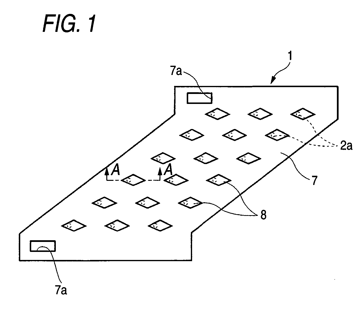
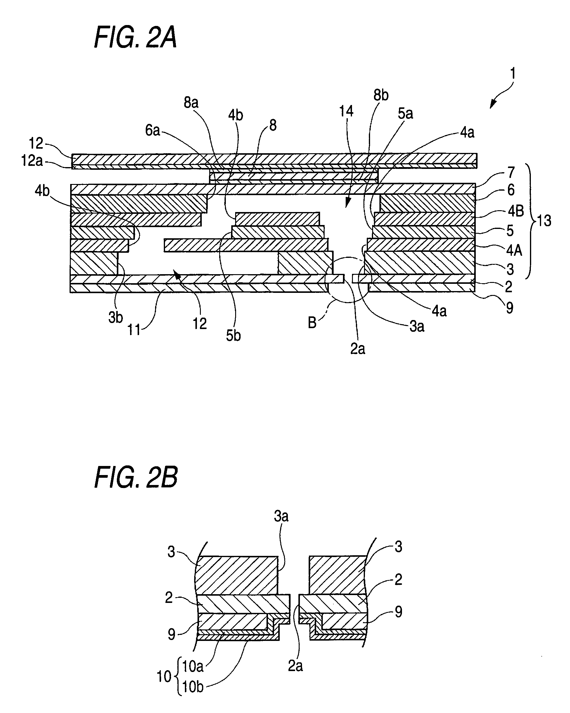
[0027]FIGS. 1 and 2 show a liquid droplet ejection head of a first embodiment of the invention. FIG. 1 is a plan view, FIG. 2A is a section view taken along the line A-A in FIG. 1, and FIG. 2B is a detail view of a portion B of FIG. 2A.

[0028]As shown in FIG. 1, the liquid droplet ejection head 1 has; a vibration plate 7 which has an approximately parallelogram shape; plural piezoelectric elements 8 which are arranged on the vibration plate 7; and plural nozzles 2a which are formed at positions corresponding to the piezoelectric elements 8. When one of the piezoelectric elements 8 is driven, a liquid stored in the head is ejected as a liquid droplet from the corresponding one of the nozzles 2a. The reference numeral 7a denotes a supply hole which is disposed in the vibration plate 7, and through which the liquid is supplied from a liquid tank (not shown) to the interior of the head 1.

[0029]As shown in FIG. 2A, the liquid droplet ejection...

second embodiment

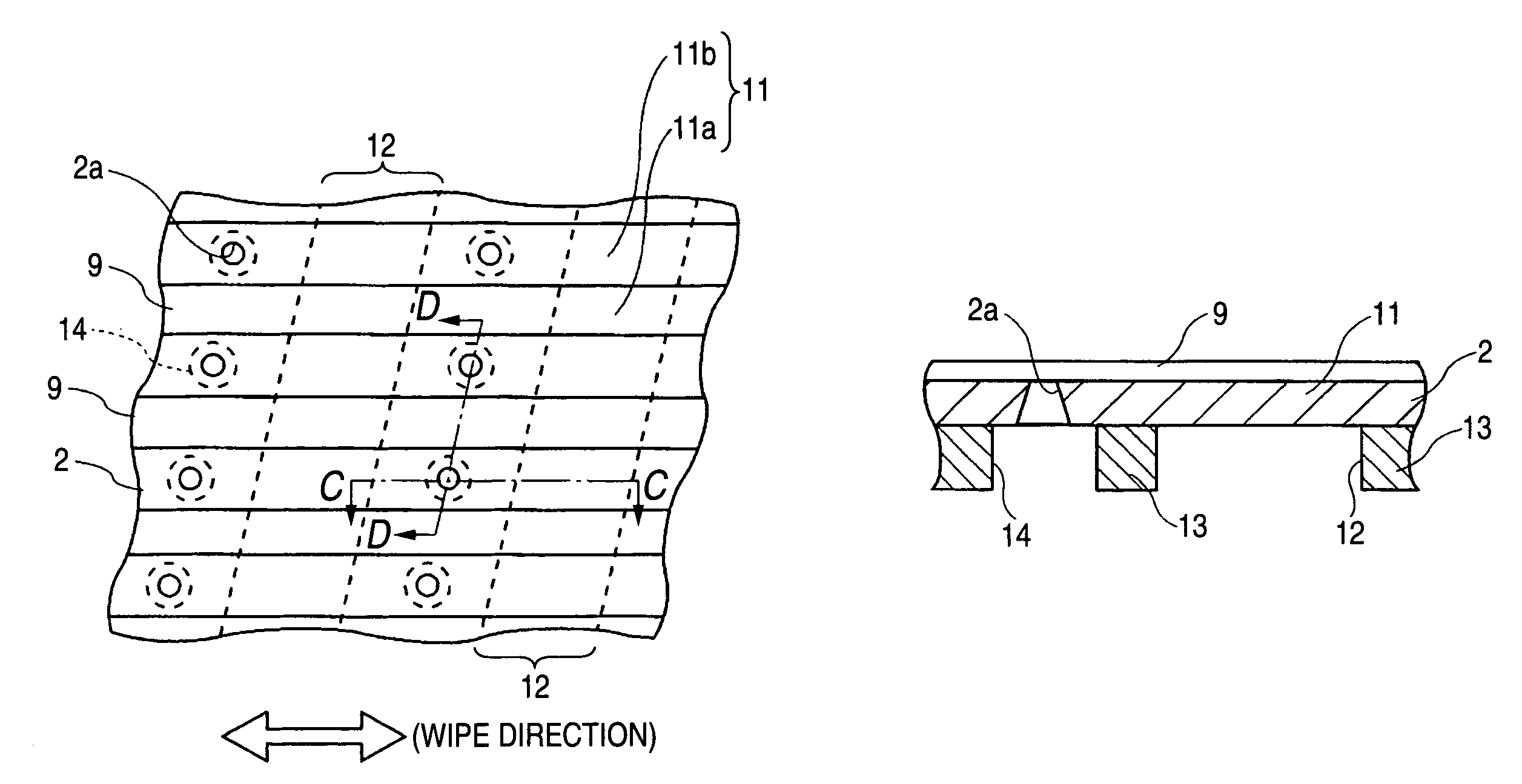
[0060]FIG. 6 shows a damper portion in a second embodiment, FIG. 6A is a plan view, FIG. 6B is a section view taken along the line E-E in FIG. 6A, FIG. 6C is a section view taken along the line F-F in FIG. 6A, and FIG. 6D is a section view taken along the line G-G in FIG. 6A.

[0061]As shown in FIG. 6, the second embodiment is identical with the first embodiment except that, in the first embodiment, the disposition (opening) shape of the protection member 9 is formed as a shape which obliquely extends, and exerts the same effects.

third embodiment

[0062]FIG. 7 shows a damper portion in a third embodiment, FIG. 7A is a plan view, FIG. 7B is a section view taken along the line H-H in FIG. 7A, and FIG. 7C is a section view taken along the line I-I in FIG. 7A.

[0063]As shown in FIG. 7, the third embodiment is identical with the first embodiment except that the disposition (opening) width of the protection member 9 in the first embodiment is configured so as to be changed, and exerts the same effects. Namely, the third embodiment is identical with the first embodiment except that the opening width of the protection member 9 in the damper function portion 11b is set to, for example, 350 μm, and that of the protection member 9 in the periphery of the nozzle 2a is set to, for example, 200 μm.

Effects of Third Embodiment

[0064]Since the opening width of the protection member 9 in the damper function portion 11b is increased (the disposition width of the protection member 9 is reduced), the reinforcement effect of the damper portion 11 ca...


PUM

PropertyMeasurementUnit
thicknessaaaaaaaaaa
thicknessaaaaaaaaaa
thicknessaaaaaaaaaa

Abstract

A liquid droplet ejection head includes: a nozzle plate that has a plurality of nozzles ejecting a liquid droplet; a flow path member that includes: pressure generating chambers that communicate with the nozzles; and liquid supply paths through which liquid is supplied to the pressure generating chambers; and a damper portion that is disposed in at least one part of a region, the region being on the nozzle plate, corresponding to the liquid supply paths, the damper portion reducing a fluctuation of an ejection amount of the liquid droplets to enable stable ejection.

Description

CROSS-REFERENCE TO RELATED APPLICATIONS[0001]This application is based on and claims priority under 35 U.S.C. 119 from Japanese Patent Application No. 2006-183639 filed Jul. 3, 2006.BACKGROUND[0002]1. Technical Field[0003]The present invention relates to a liquid droplet ejection head, an apparatus for ejecting liquid droplet, and a method of producing a liquid droplet ejection head, and more particularly to a liquid droplet ejection head in which variation of the ejection amount of liquid droplets can be absorbed to enable stable ejection and printing of high quality, and which is simple and economical, an apparatus for ejecting liquid droplet, and a method of producing such a liquid droplet ejection head.[0004]2. Related Art[0005]An inkjet head comprising nozzles for ejecting an ink, pressure generating chambers communicating with the nozzles, and an ink supply path for supplying the ink to plural pressure generating chambers is used. In such an inkjet head, when the ejection amou...

Claims


Application Information

Patent Timeline
Patent Type & Authority Patents(United States)
IPC IPC(8): B41J2/17B41J2/14B41J2/045
CPCB41J2/055B41J2/14233Y10T29/49401B41J2202/11B41J2002/14459
Inventor KATAOKA, MASAKIFUKUNAGA, HIDEKIINOUE, HIROSHINISHIMURA, YUJIHIRAKATA, SUSUMUIMAZEKI, ATSUMICHI
Owner FUJIFILM BUSINESS INNOVATION CORP
Why Eureka
Try Eureka