

Cutting tool for rough and finish milling
a cutting tool and finish technology, applied in the field of single-milling cutters, can solve the problems of time-consuming and burdensome tasks of finishing milling cutters
- Summary
- Abstract
- Description
- Claims
- Application Information
AI Technical Summary
Problems solved by technology
Method used
Image

Examples
Embodiment Construction
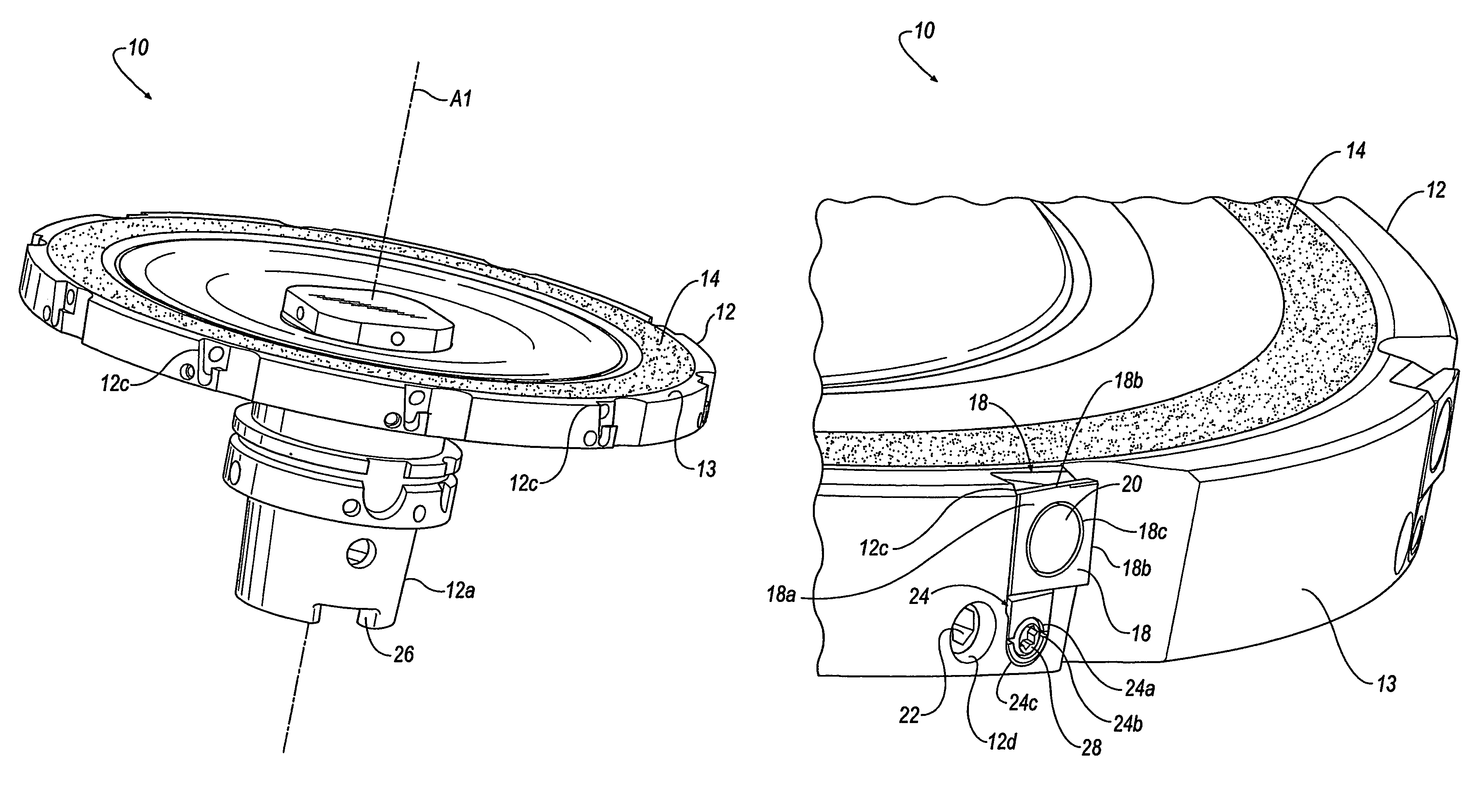
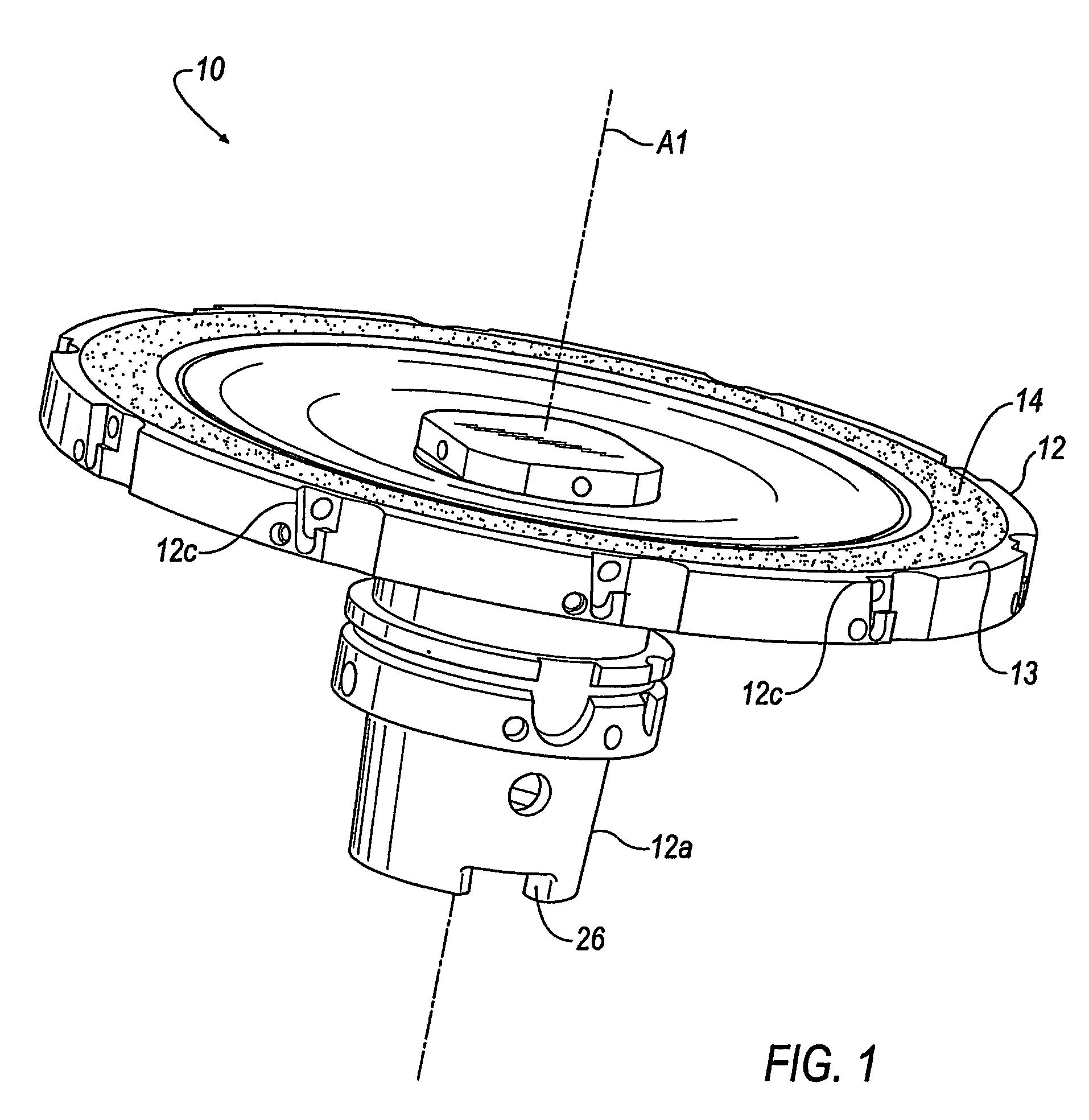
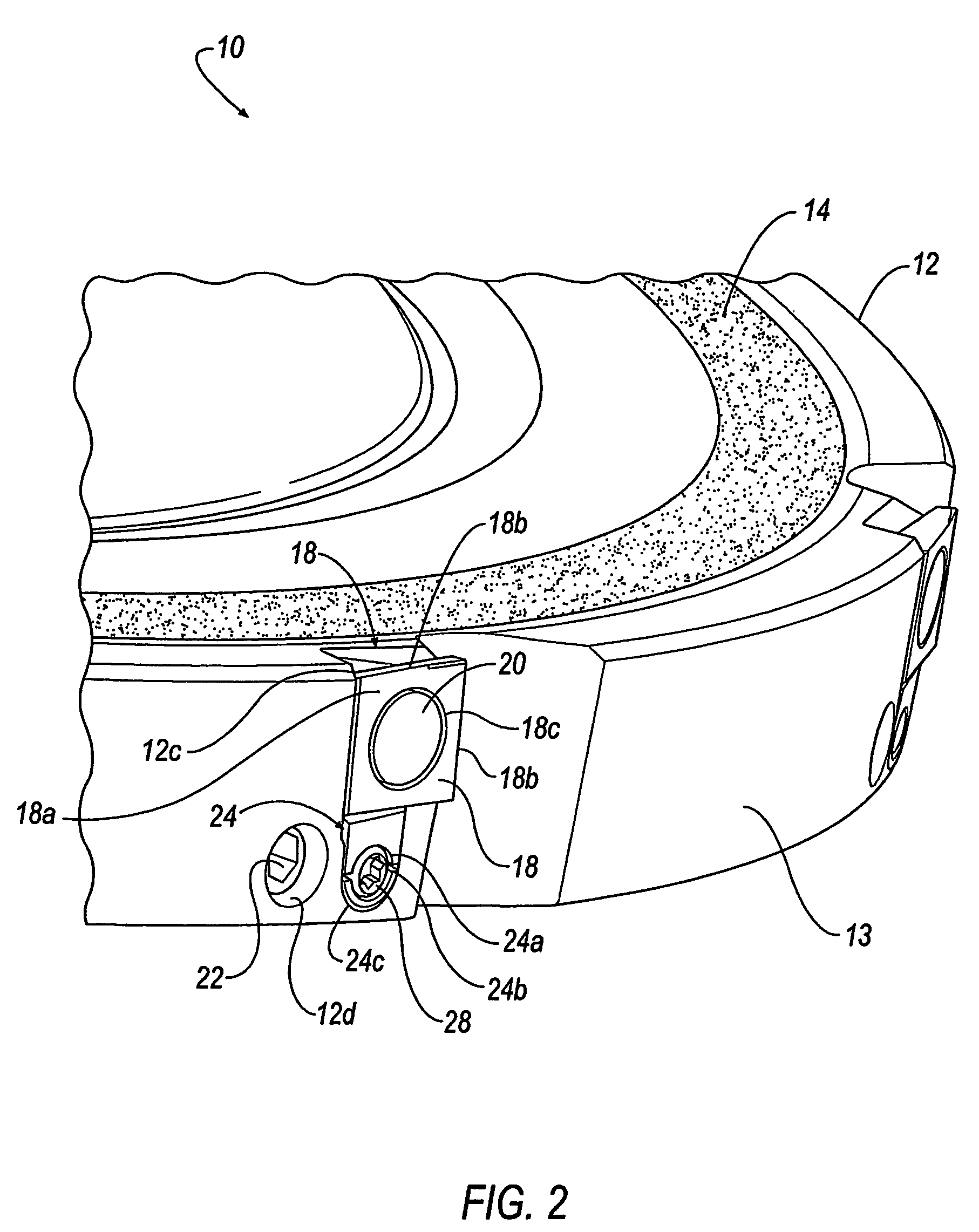
[0010]With reference now to FIG. 1, wherein like numerals designate like components throughout all of the several figures, there is illustrated a cutting tool according to a preferred embodiment of the invention. The cutting tool illustrated is in the form of a milling cutter 10 that functions to perform both a rough milling operation and a finish milling operation. The operation may be performed in a single pass or in two or more passes. For example, the milling cutter 10 may first perform a rough milling operation on a work piece in an initial pass and then in one or more subsequent passes perform a finish milling operation on a work piece.
[0011]The milling cutter 10 includes a cutter body 12 having at least two concentric annular operational rings 13, 14. An outer ring 13, which is defined by the outer periphery of the cutter body 12, is provided for the rough milling operation. An inner ring, which is defined as a finishing ring 14, is provided for the finish milling operation. ...
PUM
| Property | Measurement | Unit |
|---|---|---|
| abrasive | aaaaa | aaaaa |
| time | aaaaa | aaaaa |
| shape | aaaaa | aaaaa |
Abstract
Description
Claims
Application Information