Voltage/current regulator improvements for an implantable medical device
What is AI technical title?
AI technical title is built by Patsnap AI team. It summarizes the technical point description of the patent document.
a technology of voltage/current regulator and medical device, which is applied in the field of implantable medical device, can solve the problems of delayed stimulation pulse and damage to the tissue around the first stimulated electrod
Active Publication Date: 2010-09-28
MEDTRONIC INC
View PDF23 Cites 69 Cited by
Summary
Abstract
Description
Claims
Application Information
AI Technical Summary
This helps you quickly interpret patents by identifying the three key elements:
Problems solved by technology
Method used
Benefits of technology
Benefits of technology
[0015]In the embodiment of the invention, apparatus and method provide flexibility in generating a stimulation waveform to an electrode of an implantable medical device such as an Implantable Neuro Stimulator (INS). The stimulation waveform comprises at least one stimulation pulse. The embodiment of the invention supports a generation of a stimulation pulse in which an amplitude and an electrical polarity of the stimulation pulse can be dynamically changed. The embodiment comprises a capacitor arrangement, a regulator and a switching array. With the embodiment, the capacitor arrangement can be reconfigured with respect to an electrical reference through the switching array in order for the regulator to deliver the stimulation pulse to a pair of electrodes.
Problems solved by technology
The tissue around a first stimulated electrode can be damaged by a charge accumulation as a result of electrical stimulation.
However, a stimulation pulse may be delayed as a result of increasing the passive recharge interval.
Method used
Image
Click on the blue label to locate the original text in one second.
Reading with bidirectional positioning of images and text.
Examples
Embodiment Construction
[0044]The entire contents of U.S. application Ser. No. 10 / 133,702, filed Apr. 26, 2002, is hereby incorporated by reference.
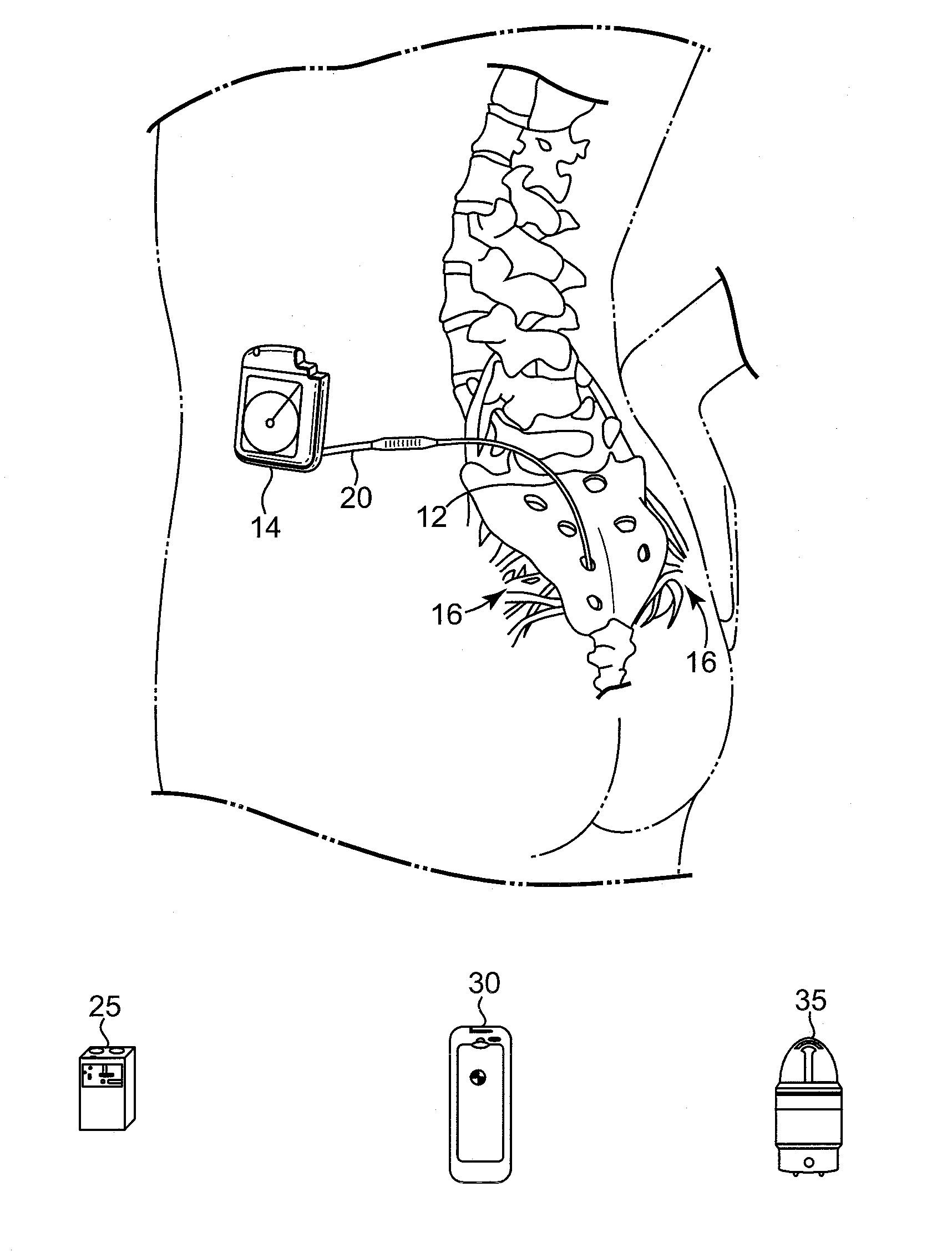
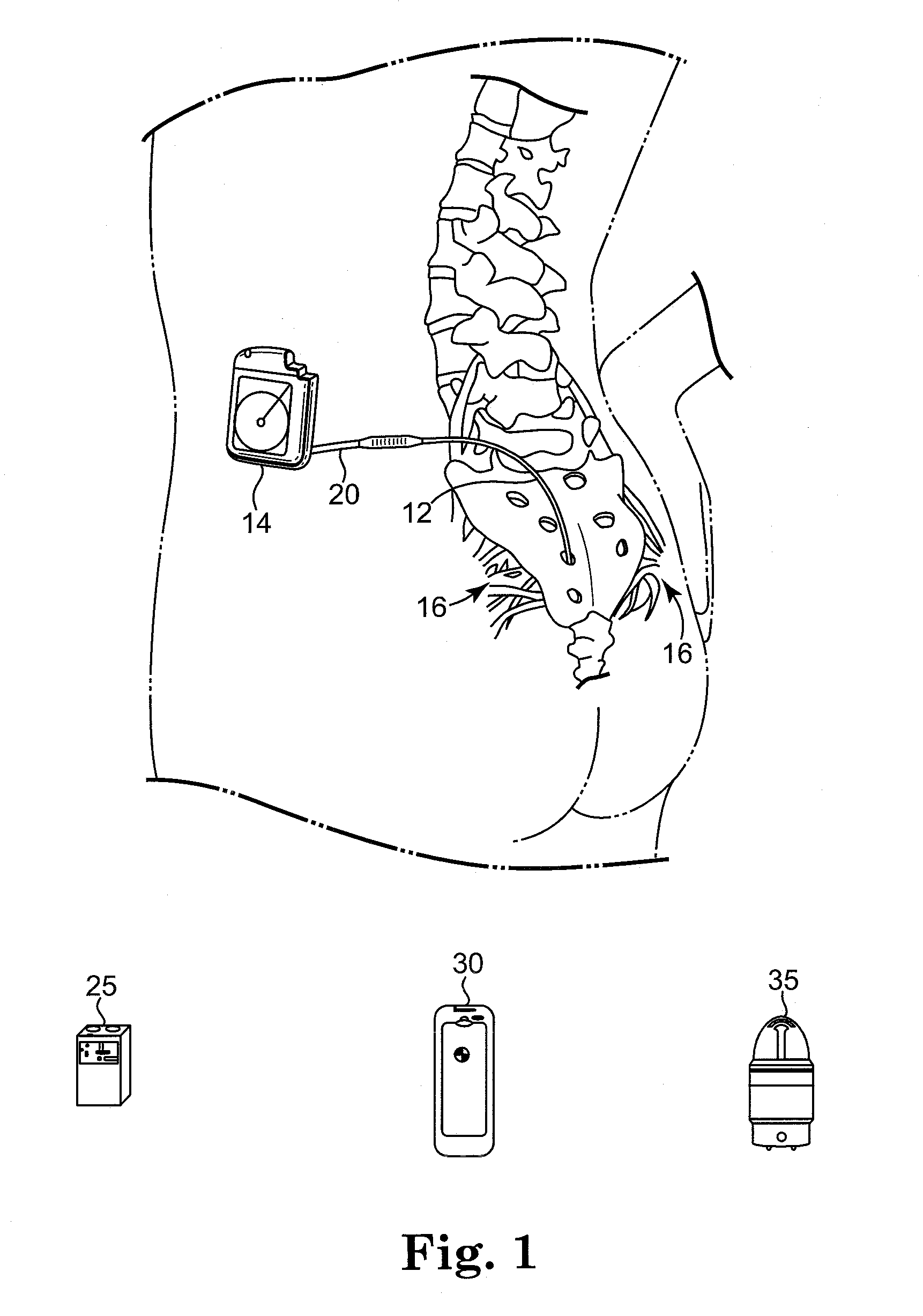
[0045]Overall Implantable Medical Device System. FIG. 1 shows the general environment of an Implantable Neuro Stimulator (INS) medical device 14 in accordance with a preferred embodiment of the present invention. The neurostimulation system generally includes an INS 14, a lead 12, a lead extension 20, an External Neuro Stimulator (ENS) 25, a physician programmer 30, and a patient programmer 35. The INS 14 preferably is a implantable pulse generator that will be available from Medtronic, Inc. with provisions for multiple pulses occurring either simultaneously or with one pulse shifted in time with respect to the other, and having independently varying amplitudes and pulse widths. The INS 14 contains a power source and electronics to send precise, electrical pulses to the spinal cord, brain, or neural tissue to provide the desired treatment therapy. In the embodi...
PUM
Abstract
Apparatus and method provide flexibility in generating a stimulation waveform to an electrode of an implantable medical device. The stimulation waveform comprises at least one stimulation pulse. The embodiment of the invention supports a generation of a stimulation pulse in which an amplitude and an electrical polarity of the stimulation pulse can be dynamically changed. The embodiment comprises a capacitor arrangement, a regulator and a switching array. The capacitor arrangement can be reconfigured with respect to an electrical reference through the switching array in order for the regulator to deliver the stimulation pulse to a pair of electrodes. In another embodiment, a plurality of stimulation waveforms are generated in which different stimulation waveforms are associated with different electrodes. With the embodiment, a plurality of regulators are connected and reconfigured to the capacitor arrangement in order that the different stimulation waveforms are generated by different regulators.
Description
RELATED APPLICATIONS[0001]This application is a continuation of U.S. patent application Ser. No. 10 / 133,702, filed Apr. 26, 2002 and claims priority therefrom.[0002]This disclosure is related to the following co-pending applications:[0003]a. “Recharge Delay for an Implantable Medical Device” by inventors Goblish, et al., having U.S. patent application Ser. No. 10 / 133,703, and filed on Apr. 26, 2002;[0004]b. “Independent Therapy Programs in an Implantable Medical Device” by inventors Goblish, et al., having U.S. patent application Ser. No. 10 / 133,884, and filed on Apr. 26, 2002;[0005]c. “Detection of Possible Failure of Capacitive Elements in an Implantable Medical Device” by inventors Heathershaw, et al., having U.S. patent application Ser. No. 10 / 133,925, and filed on Apr. 26, 2002;[0006]d. “Wave Shaping for an Implantable Medical Device” by inventors Goblish, et al., having U.S. patent application Ser. No. 10 / 133,513, and filed on Apr. 26, 2002;[0007]e. “Automatic Waveform Output ...
Claims
Application Information
Patent Timeline
Application Date:The date an application was filed.
Publication Date:The date a patent or application was officially published.
First Publication Date:The earliest publication date of a patent with the same application number.
Issue Date:Publication date of the patent grant document.
PCT Entry Date:The Entry date of PCT National Phase.
Estimated Expiry Date:The statutory expiry date of a patent right according to the Patent Law, and it is the longest term of protection that the patent right can achieve without the termination of the patent right due to other reasons(Term extension factor has been taken into account ).
Invalid Date:Actual expiry date is based on effective date or publication date of legal transaction data of invalid patent.

