Methods and systems for physical hierarchy configuration engine and graphical editor

a configuration engine and graphical editor technology, applied in the field of computer aided design, can solve the problems of time-consuming, difficult mapping to multiple technology libraries, and difficulty in mapping a single generic logical library to multiple technology-specific physical libraries,

Active Publication Date: 2010-09-28
CADENCE DESIGN SYST INC
View PDF14 Cites 22 Cited by
  • Summary
  • Abstract
  • Description
  • Claims
  • Application Information

AI Technical Summary

Benefits of technology

[0013]In one embodiment, annotations required to map from logical design to physical design may be stored in a separate design view. This design view is called a physical configuration view. The annotations required to map logical library cells to physical library ce

Problems solved by technology

This might, in some cases, be time consuming, especially in a large design.
Additionally, in some cases, mapping to multiple technology libraries may be difficult because only one set of mapping information may be stored as properties in each logical library cell or instance.
In some cases mapping a single generic logical library to multiple technology-specific physical libraries may

Method used


Image

  • Methods and systems for physical hierarchy configuration engine and graphical editor
  • Methods and systems for physical hierarchy configuration engine and graphical editor
  • Methods and systems for physical hierarchy configuration engine and graphical editor

Examples


Embodiment Construction

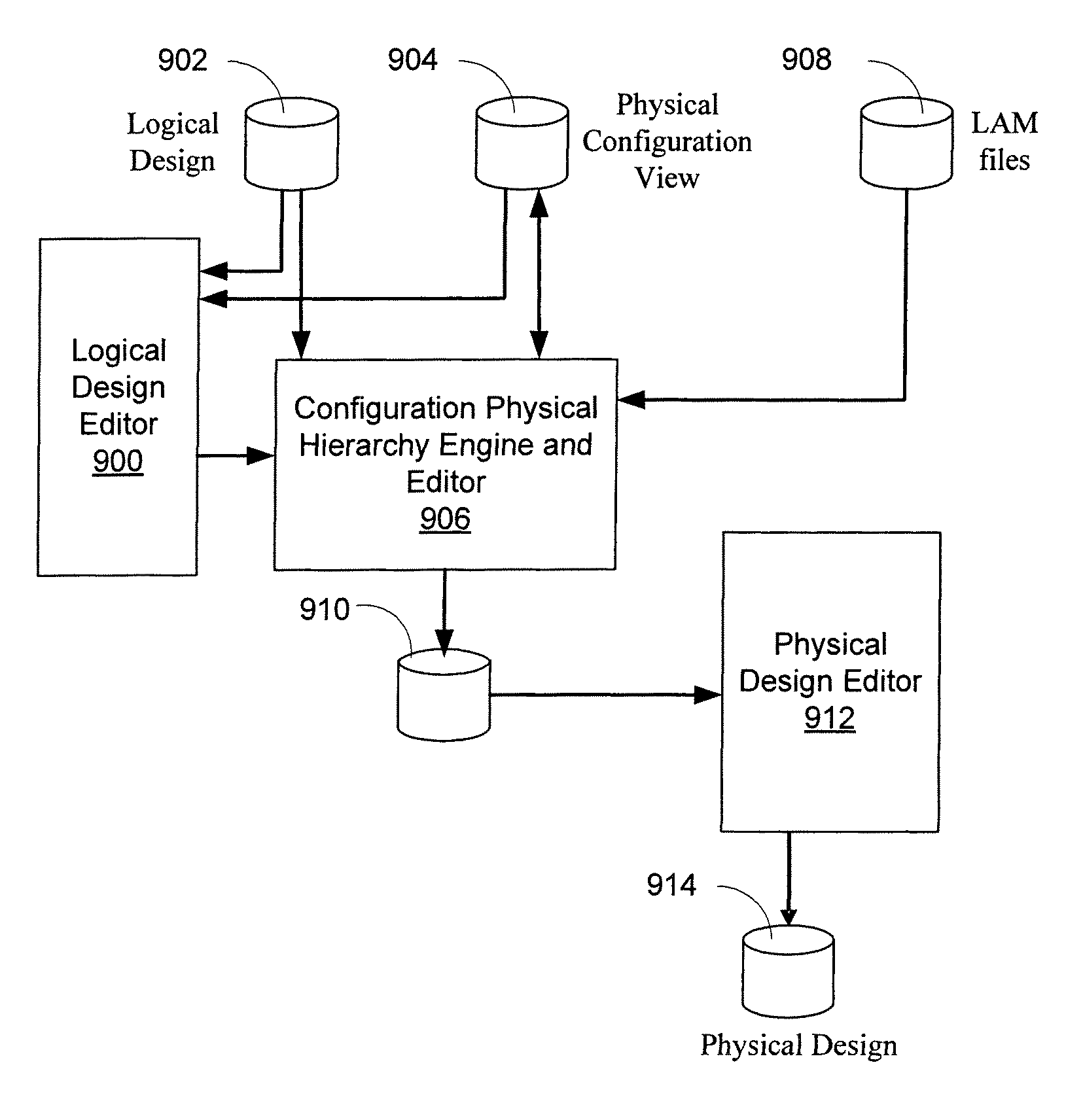
[0012]According to one embodiment of the invention, a new method to address configuring a logical design and libraries of design elements with additional information is proposed that may be used to create a physical design from that logical design. Logical designs might be generic, i.e. not targeted to a specific technology process, while physical design libraries are normally targeted towards specific technology. Consequently, there can be a mapping from the cells in a logical library to cells that correspond to their implementation in a physical library.

[0013]In one embodiment, annotations required to map from logical design to physical design may be stored in a separate design view. This design view is called a physical configuration view. The annotations required to map logical library cells to physical library cells may be stored in an XML file known as a library attributes mapping file (“LAM file”). By using a separate design view it may be possible to define and edit the mapp...


PUM


Abstract

In one embodiment a new method to address configuring a logical design and libraries of design elements with additional information is proposed that may be used to create a physical design from that logical design. Logical designs may be generic, while physical design libraries are normally targeted towards specific technology. Consequently, there can be a mapping from the cells in a logical library to cells which correspond to their implementation in a physical library. In one embodiment, annotations required to map from logical design to physical design may be stored in a separate design view. In one embodiment the user can modify the physical mapping attributes of cells, instances, and occurrences in the logical design and save the modifications back to the physical configuration view.

Description

TECHNICAL FIELD[0001]The present invention relates to computer-aided design and more particularly, some embodiments relate to design configuration within a computer aided design system.DESCRIPTION OF THE RELATED ART[0002]In some design systems, a logical design may be constructed from instances of cells in a logical design library. For example, a library can contain predefined logical functions that can be combined together to create a logical design. The logical design can then be mapped to an actual physical design. The physical design may include the actual placement of transistors on a die, for example. A logical design can have multiple physical designs. In other words, a logical design might be implemented in a number of different ways. For example, physical elements such as transistors, logic gates, input / output pins, etc. can be altered, placed at different locations on a die, different types of technologies can be used, and so on. Additionally, a logical design can also hav...

Claims


Application Information

Patent Timeline
IPC IPC(8): G06F17/50
CPCG06F17/505G06F17/5072G06F30/327G06F30/392
Inventor FERGUSON, KENNETHMACKIE, KENNETHLAMANT, GILLES S. C.NAIR, SRAVASTI GUPTA
Owner CADENCE DESIGN SYST INC
Why Eureka
Try Eureka