Elevator and pulley assembly for use in an elevator

a technology for elevators and pulleys, which is applied in the direction of elevators, building lifts, transportation and packaging, etc., can solve problems such as space problems

Inactive Publication Date: 2010-10-05
INVENTIO AG
View PDF11 Cites 12 Cited by
  • Summary
  • Abstract
  • Description
  • Claims
  • Application Information

AI Technical Summary

Benefits of technology

[0005]The use of several flat belts, which are arranged parallel to one another, as supporting and driving means enables use of a drive pulley as well as supporting and deflecting rollers with small diameters. A small drive pulley diameter enables use of drive motors or drive units with small dimensions, and with small supporting and deflecting rollers optimum use can be made of the available installation space. It is achieved by the elevator or roller arrangement according to the invention that the installation space required laterally adjacent to the elevator car for the deflection of several parallel belts can be kept as small as possible and simple roller frames of small construction can be used. Moreover, the invention makes it possible to arrange the deflecting rollers, which are present in the region of the under-looping on respective sides of the elevator car, along a common axis.
[0010]Advantageously, the rollers of the fixed (multi-axial) roller groups lie within two parallel planes spaced by the roller width, wherein the axes of the rollers are oriented at right angles to these planes. Installation space required for the roller group is thus minimized.
[0012]Advantages for setting and retightening of the belts result from the fixing points of all belts being arranged directly adjacent to and / or on a fixing point support. Through connection of the fixing point support with one of the guide rails it is possible to avoid the need for the loading of the support by the belt forces to be absorbed exclusively by the shaft wall of the elevator installation.
[0013]According to a further preferred form of embodiment the belts are provided at at least one of the main surfaces thereof with ribs and grooves extending in belt longitudinal direction, and the drive pulley as well as the supporting and deflecting rollers have corresponding complementary ribs and grooves along the circumference of their running surfaces. The guidance characteristics between the rollers and the belt as well as the traction capability between drive pulley and belt can be substantially improved by this measure.

Problems solved by technology

Space problems arise in 4:1 suspensions of that kind, but also in other arrangements, particularly when the elevator system does not have an engine room.

Method used


Image

  • Elevator and pulley assembly for use in an elevator
  • Elevator and pulley assembly for use in an elevator
  • Elevator and pulley assembly for use in an elevator

Examples


Embodiment Construction

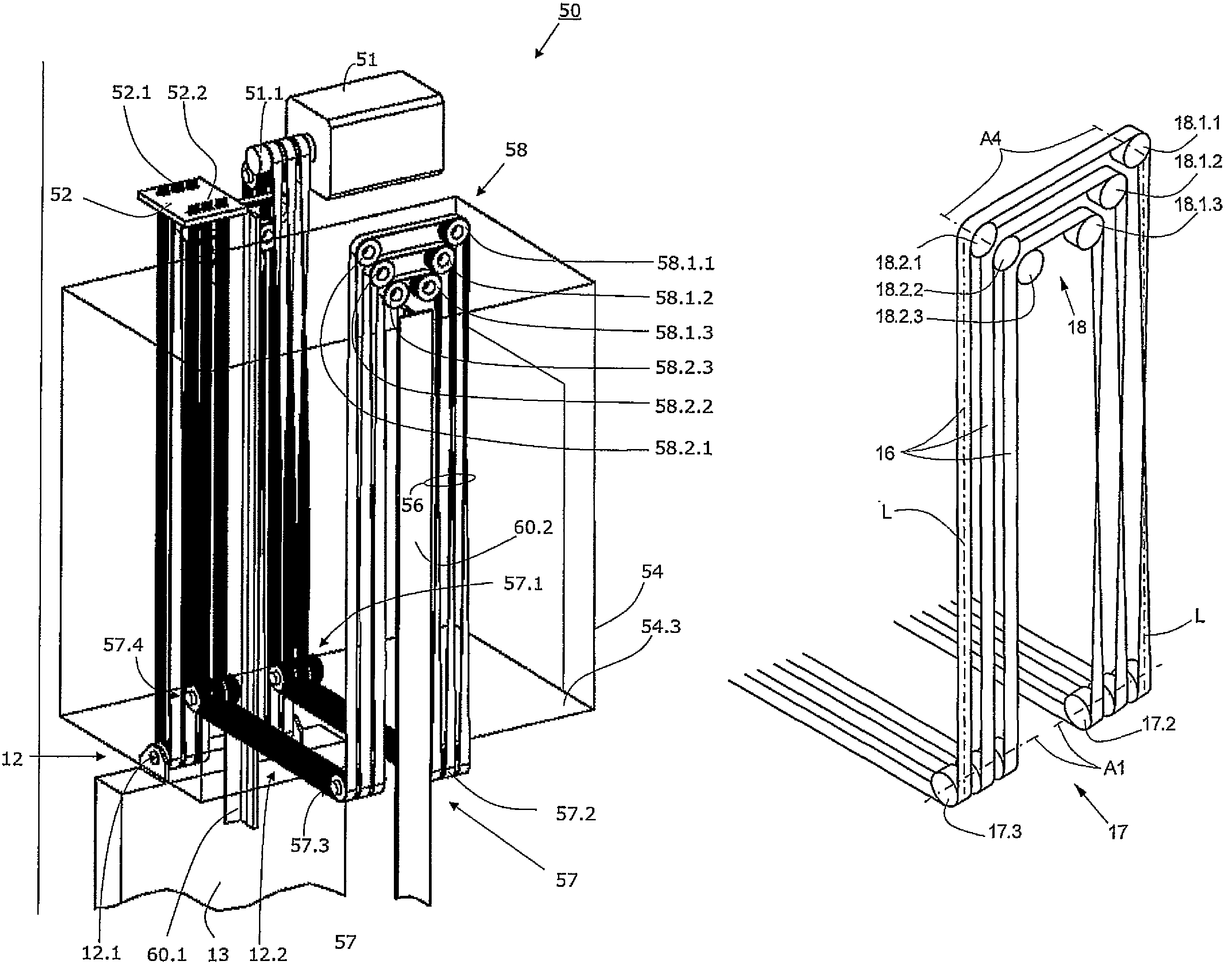
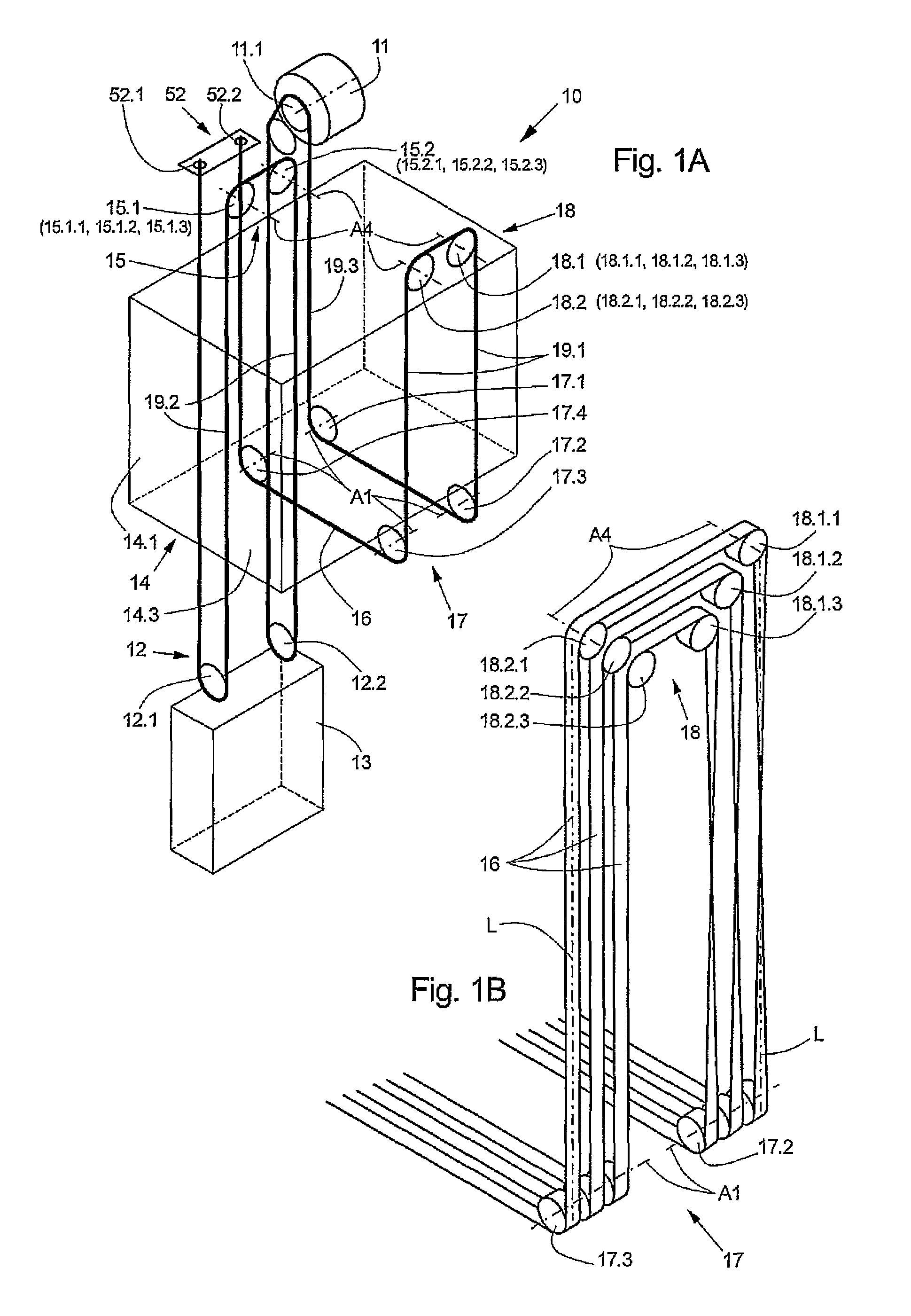
[0026]FIG. 1A shows a support means arrangement for an elevator 10 with an elevator car 14 and a counterweight 13 according to a first form of embodiment of the present invention. For the purpose of better clarity, the support means strands, which comprise several belts 16, and the associated supporting and deflecting rollers are illustrated in each instance by a single line or a single circle. FIG. 1B shows, in an enlarged detail of FIG. 1A, the effective arrangement of the belts 16 and the supporting and deflecting rollers in a region which comprises a fixed (multi-axial) roller group 18 with the individual rollers 18.1.1-18.2.3 and two (coaxial) roller units 17.2, 17.3 of a movable—i.e. belonging to the elevator car 14—car roller group 17.

[0027]Present below the elevator floor 14.3 is a movable car roller group 17 which is connected with the floor and consists of four coaxial roller units 17.2, 17.4 and 17.2, 17.3. The axes A1 of rotation of the four coaxial roller units extend s...


PUM


Abstract

An elevator comprises an elevator car and support belts that form a 4:1 suspension for the elevator cabin and that are looped several times beneath the elevator car. Several parallel, flat belts are used and the rollers of at least one fixed roller group that diverts the belts are positioned in such a way that the belt sections of the parallel belts lie vertically above one another in the vicinity of the belt diversion.

Description

BACKGROUND OF THE INVENTION[0001]The present invention relates to an elevator and a roller arrangement for use in an elevator. The invention is particularly, but not exclusively, suitable for use in conjunction with an elevator system without an engine room.[0002]Use is made, particularly for elevators which are designed for moving larger loads, of a so-termed 4:1 suspension in which the region, which is driven by the drive pulley, of the supporting and / or driving element moves four times faster than the elevator car. Such a suspension is schematically shown in European patent EP 588 364.[0003]Space problems arise in 4:1 suspensions of that kind, but also in other arrangements, particularly when the elevator system does not have an engine room. The more elevator components have to be accommodated in the shaft, the more important it is to find a space-saving approach.SUMMARY OF THE INVENTION[0004]It is now an object of the present invention to propose an improved elevator of the kind...

Claims


Application Information

Patent Timeline
Patent Type & Authority Patents(United States)
IPC IPC(8): B66B11/08B66B11/04
CPCB66B11/008B66B7/06B66B11/08B66B11/00
Inventor FISCHER, DANIEL
Owner INVENTIO AG
Why Eureka
Try Eureka