Electromagnetic linear optical positioner

a positioner and linear technology, applied in the field of electromagnetically linear optical positioners, can solve the problems of insufficient light coupled through the fibre for the intended purpose, many fibre-optic micromechanical devices that do not fit the small order of magnitude, and the design of the positioner places limits on the reduction of switch size, so as to achieve the effect of maximizing the force applied by means of the magnet, compact structure and reduced construction

Inactive Publication Date: 2004-09-28
MICROCUT AG
View PDF11 Cites 7 Cited by
  • Summary
  • Abstract
  • Description
  • Claims
  • Application Information

AI Technical Summary

Benefits of technology

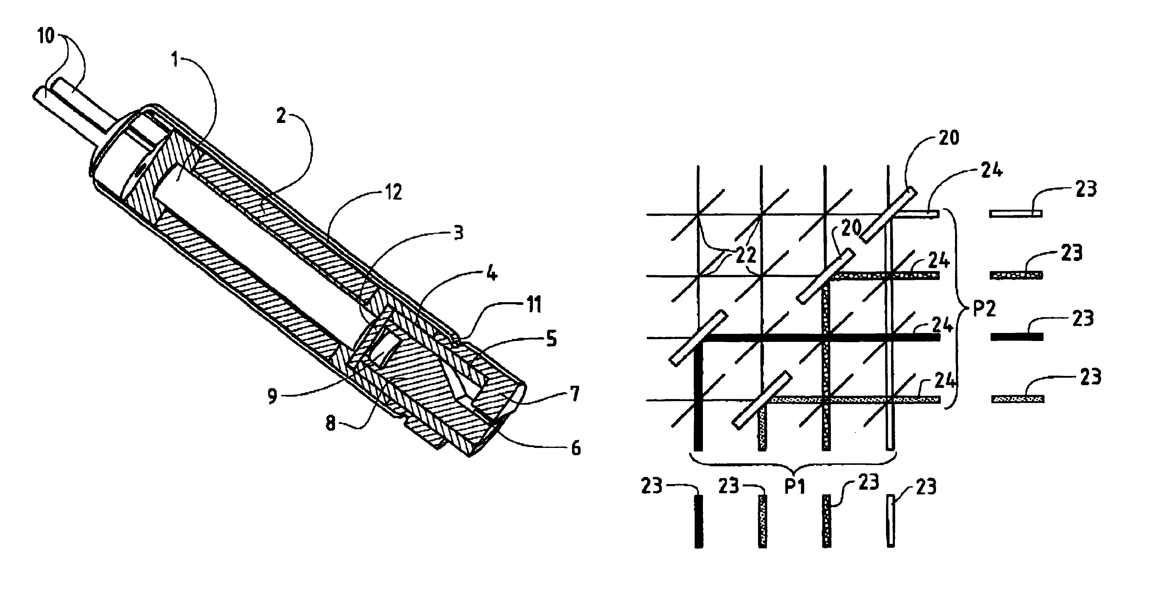
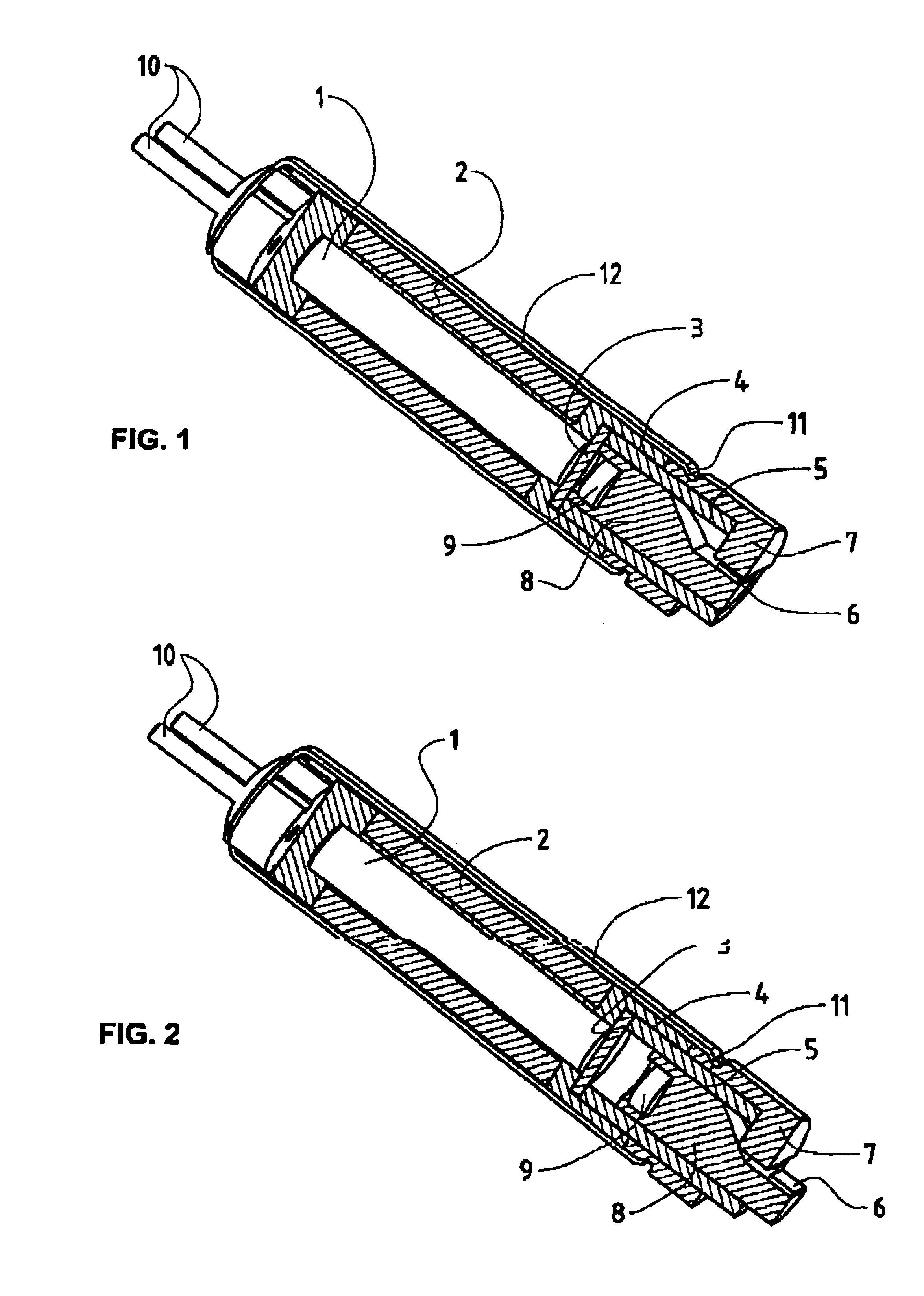
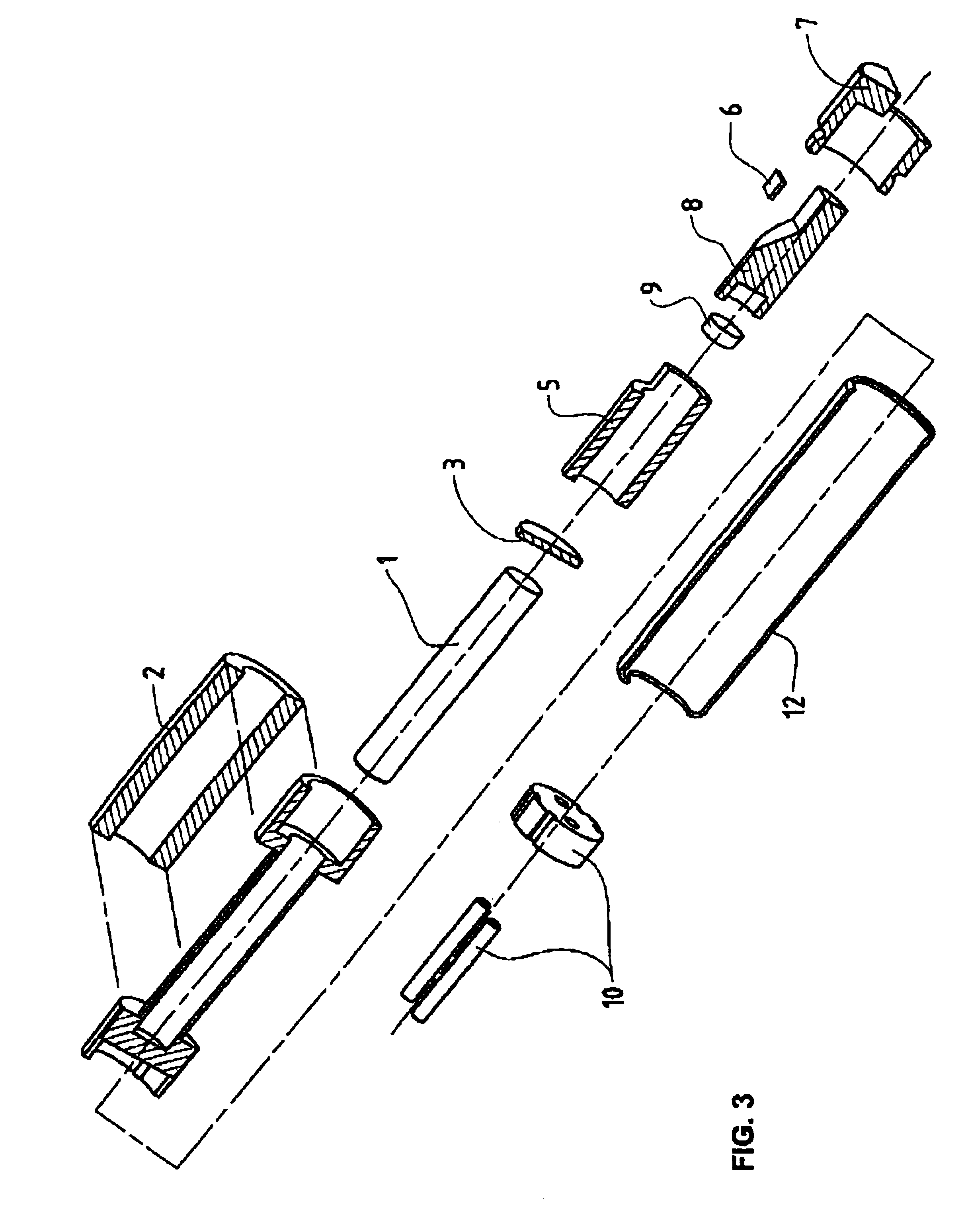
are also achieved in particular in that an electromagnetic positioner or actuator comprises a piston, which piston is movable between a first and a second predefined position and which piston is held by a piston guide, the movable piston comprising a permanent magnet directed perpendicular to the direction of movement the piston comprising an electromagnetic coil, capable of polarity reversal, in the direction of movement of the piston, by means of which coil, in accordance with its magnetisation, the piston is movable from the one predefined position into the other predefined position, and the coil core, capable of polarity reversal, possesses a magnetic remanence by means of which the movable piston is fixable in one of the two predefined positions when the coil is switched off, i.e. not energized. The piston can be of cylindrical design with a cylindrical piston guide. It can also have a different shape such as, e.g. rectangular. The permanent magnet can be disposed on the piston at the end, for example, it also being conceivable for it to be integrated in the piston at a different place. It can be advantageous, if said permanent magnet and / or said electromagnetic coil are axially magnetized in the direction of motion of said piston. This has inter alia the advantage that the application of force by means of the magnet can be maximized. The permanent magnet of the piston can have e.g. an inductance (B) of 1.2-1.6 T and a coercive field of 940 000-1 000 000 A / m. This has the advantage that, with the typical dimensions for a micro linear positioner, it can correspond to the required signal strength. The magnet core, capable of polarity reversal, can consist e.g. at least partially of a semi-hard magnetic material. The piston and the magnet coil with magnetic core can be separated in the piston e.g. through spacers, which are installed between the piston guide and the magnet coil with the coil core. This has inter alia the advantage that during positioning the piston in the first position, the magnet coil with coil core are not damaged and a predefined spacing is kept between coil core and permanent magnet. In a preferred embodiment, the piston guide is achieved by means of a housing of the piston. Since, in contrast to the state of the art, a magnetic core, capable of polarity reversal, with remanence, is used, instead of two magnets, to bring the piston into one of the two positions, the piston can be of much smaller construction and more compact, which also means shorter reaction times for the piston. Smaller and more economical optical switches can also be created thereby.
In another embodiment variant, the piston and / or the piston housing is made at least partly of ceramic. This has the advantage, among other things, that the friction resistance in the positioner can be greatly reduced and the components have a much smaller thermal expansion coefficient. On the one hand, this enlarges the possible field of application for the positioner. On the other hand, the wear and tear within the positioner is moreover reduced.
In a further embodiment variant, the piston comprises a lateral notching and the piston housing has a stop element by means of which the second predefined position of the piston can be set, the stop element abutting the piston at the notching. This has the advantage, among other things, that the positioner is easy to achieve and produce. This also brings with it, among other things, a reduction of the manufacturing costs.
In an embodiment variant, the stop element has magnetic properties which assist to hold the piston in the second position. This has the advantage inter alia that possible recoil momentum, occurring through the stopping of the piston in the second position, can be compensated.
In an embodiment variant, the magnet coil with magnetic coil core has an impulse time 2 to 3 times longer than necessary for moving the piston from one position into the other position. This has the advantage, among other things, that possible recoil momentum of the piston when impinging upon the spacer or the stop element can be compensated.

Problems solved by technology

However, many fibre-optic micromechanical devices do not fit that small order of magnitude, and micromechanical optical switches of larger dimensions are needed where thermal or piezoelectric actuators no longer can be used.
If the free-space-to-fibre coupling is not efficient then the amount of light coupled through the fibre might be insufficient for the intended purpose.
However, current micro positioner design places limits on switch size reductions.
Therefore, although prior devices based on current micro positioners provide switching functions, they are difficult to manufacture and limited in the reduction of their size which causes the aforementioned problems.
Furthermore, current micro positioners may be subject to temperature and environmental fluctuations, particularly because they employ materials that can expand and contract due to temperature fluctuations.
On the one hand, this enlarges the possible field of application for the positioner.

Method used


Image

  • Electromagnetic linear optical positioner
  • Electromagnetic linear optical positioner
  • Electromagnetic linear optical positioner

Examples


Embodiment Construction

Referring now to the drawings, wherein like numerals indicate like elements, FIGS. 1 up to 6 show two different embodiments of a micro positioner or actuator according to the present invention. The presently preferred embodiment of the micro actuator or positioner may be used in an optical switch module 21 to control the direction of laser beams between two collimators (not shown). However, its use is not limited. It can be used in any environment requiring a latched movement, especially one requiring a linear actuator or positioner of small size and fast switching time.

FIG. 7 is a schematic diagram showing such an optical switch module 21 with an array or matrix of fibres in the X / Y plane, such fibres A, B, C, and D, extending horizontally and crossing fibres 31, 32, 33, and 34 extending vertically in the diagram. At each of the intersections of the fibres there is a slot 22, as also shown in the enlarged view of FIGS. 11 and 12, which defines the facing ports 42 and 43 of fibres A...


PUM

PropertyMeasurementUnit
timeaaaaaaaaaa
lengthaaaaaaaaaa
sizeaaaaaaaaaa

Abstract

An electromagnetic micro positioner, e.g. for use in fibre optics, is operated by a ceramic piston (8) mounted within a ceramic cylinder (5). The piston (8) is moved by a permanent magnet (9) and an electromagnetic circuit (1 / 2). By changing the coil (2) polarity the piston (8) will either be attracted or repelled to its top or bottom position. In particular the core (1), capable of polarity reversal, has a magnetic remanence by means of which the movable piston (8) is fixable in one of the two predefined positions when the coil (2) is not energized.

Description

The present invention relates to a micro linear positioner, particularly developed for optical switches, and a manufacturing method for such micro linear positioners and / or optical switches. An electromagnetic coil moving a magnet between two latched positions in the device controls the switch-path of the positioner.DESCRIPTION OF RELATED ARTMany modern optical systems use light beams, usually laser-generated, to carry various types of information. Within the optical system, a light beam may alternate between travelling in free space and / or travelling in a fibre or another optical conductor. Amongst many other applications, the technology can be used for example to combine computers with mechanical devices such as sensors, valves, gears, mirrors, and actuators, etc. Many optical systems, such as fibre-optic micromechanical devices, e.g. in telecommunication systems etc. utilizing optical fibres, require the use of optical switches for selectively coupling signal sources to one or mo...

Claims


Application Information

Patent Timeline
Patent Type & Authority Patents(United States)
IPC IPC(8): H01F7/16H01F7/08G02B6/35H01F7/122H01F7/123H01F7/124
CPCG02B6/3572H01F7/1646G02B6/3514G02B6/3546H01F7/123H01F7/124
Inventor JONES, PETERHUG, KURTMAAG, URS
Owner MICROCUT AG
Why Eureka
Try Eureka