Tool spindle for a honing machine with a bowl-shaped holder for a honing ring

a honing machine and honing ring technology, which is applied in the direction of gear cutting machines, grinding machines, gear teeth, etc., can solve the problems of time-consuming and labor-intensive tool changes, and achieve the effects of preventing contamination of the interior of the machine housing, easy and fast changes, and good sealing

Active Publication Date: 2014-07-17
FELSOMAT
View PDF7 Cites 7 Cited by
  • Summary
  • Abstract
  • Description
  • Claims
  • Application Information

AI Technical Summary

Benefits of technology

[0020]An embodiment in which a motorized drive for the holder is provided on the outer side on the bottom part of the holder is particularly advantageous. By arranging the drive in the region of the bottom part, the construction of the tool spindle can be kept compact in the radial direction, in particular smaller than in the case of a motor arrangement located radially outward adjacent to the wall part.
[0021]Continuing from this, a preferred further development of this embodiment provides that the holder has a central shaft on the bottom part on the outer side or is connected rigidly to a shaft, and that the holder is mounted on the shaft and motor-driven by the shaft. This construction has proven itself in practice and is particularly stable.
[0022]A honing machine comprising at least one workpiece spindle and one tool spindle according to the invention described above also falls within the scope of the present invention. The honing ring (the tool) can then be changed very easily and quickly. Typically the tool spindle is orientated vertically and typically the tool spindle can be displaced by a motor and with its spindle axis is aligned vertically. Alternatively, other orientations of the tool spindle and the workpiece spindle are possible, such as horizontally.
[0023]An advantageous embodiment of the honing machine according to the invention provides that the honing machine has a machine housing in which the workpiece spindle and the tool spindle are arranged, and that a settling tank is arranged in the machine housing which surrounds the tool spindle preventing the escape of oil. As a result, contamination of the interior of the machine housing is prevented. The settling tank may be funnel-shaped in particular.
[0024]A preferred further development of this embodiment provides that the settling tank has a screen with a cut-out, by means of which the workpiece spindle with a spindle head can be inserted through the cut-out into the settling tank, so that a spindle collar on the workpiece spindle provides an oil-tight seal for the cut-out. The screen is mounted displaceably and oil-tight on the settling tank so that the screen is moved relative to the tool spindle as the workpiece spindle performs a feed movement. This design has proved itself in practice and provides the settling tank with a very good seal.

Problems solved by technology

In a tool change (exchange of honing ring), possibly the result of wear or a changeover to another type of workpiece, these screws must all be loosened and re-tightened, making the tool change quite time-consuming.

Method used


Image

  • Tool spindle for a honing machine with a bowl-shaped holder for a honing ring
  • Tool spindle for a honing machine with a bowl-shaped holder for a honing ring
  • Tool spindle for a honing machine with a bowl-shaped holder for a honing ring

Examples


Embodiment Construction

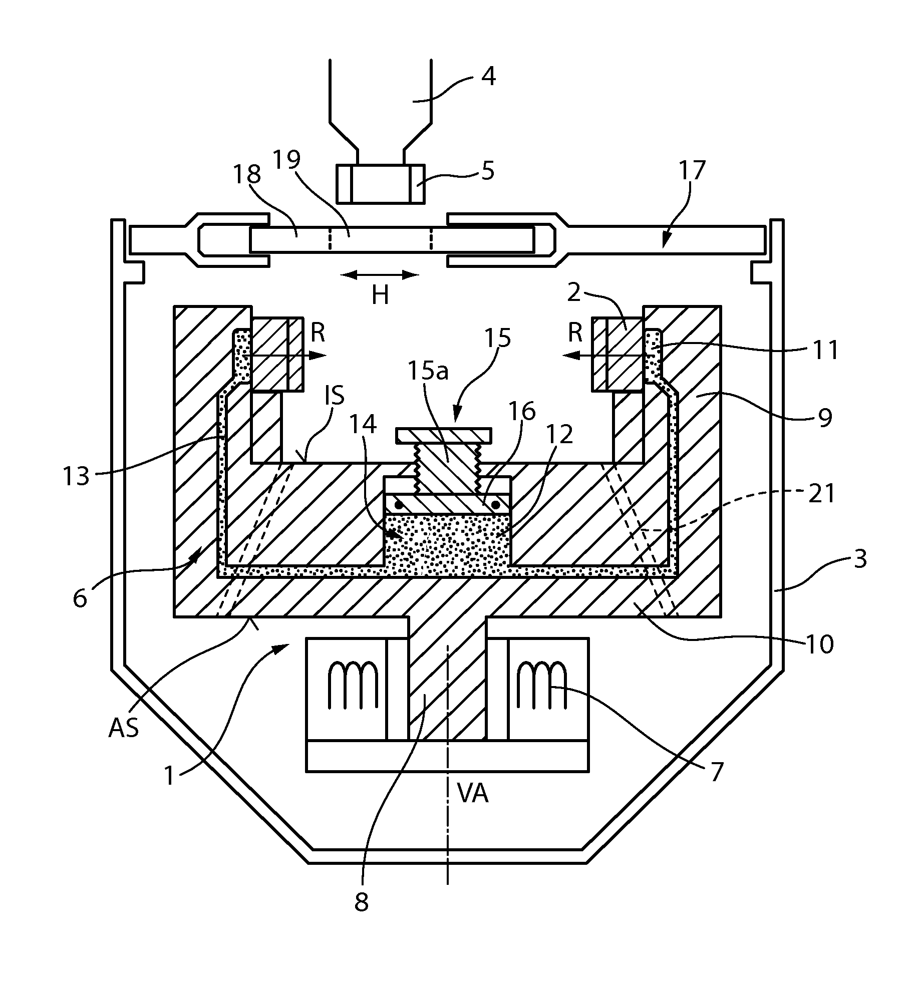
[0033]FIG. 1 shows an example of a vertical section through an embodiment of a tool spindle 1 according to the invention. A tool, namely a honing ring 2, is held in the tool spindle 1. The tool spindle 1 is arranged in a settling tank 3 which protects the surroundings of the workpiece spindle 1 from oil contamination. In the situation illustrated, a workpiece spindle 4 feeds just one workpiece, in this case a gear wheel, held on spindle head 5, so that it can undergo a honing operation, the workpiece spindle 4 still remaining outside the settling tank 3.

[0034]The tool spindle 1 comprises a holder 6 in which the honing ring 2 is retained, a shaft 8, and an electric motor 7 whereby the shaft 8 and thus also the holder 6 can be driven. The honing ring 2 then rotates correspondingly around a vertical axis VA. Here, the holder 6 is mounted entirely above shaft 8.

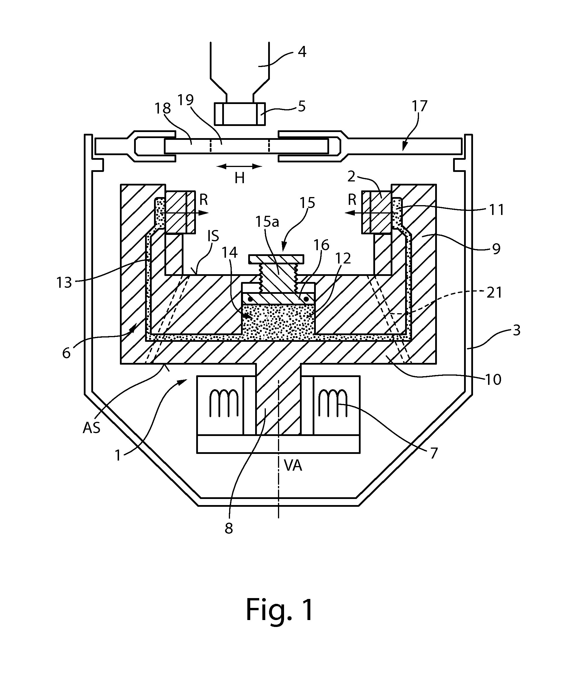
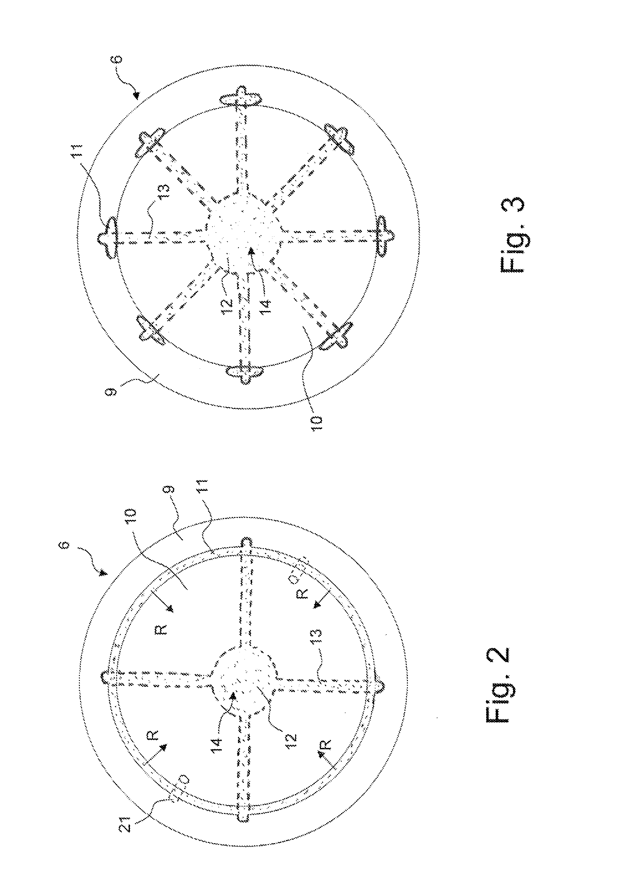
[0035]The holder 6 is constructed in the shape of a bowl and comprises a peripheral wall part 9 and a bottom part 10. Refer als...


PUM

PropertyMeasurementUnit
pressureaaaaaaaaaa
shapeaaaaaaaaaa
speedsaaaaaaaaaa

Abstract

A tool spindle for a honing machine includes a bowl-shaped holder having a circumferential peripheral wall connected to a bottom part. The bowl-shaped holder is configured to hold a honing ring on an inside of the bowl-shaped holder. At least one expansion element is formed on the inside of the bowl-shaped holder along an inner surface of the circumferential peripheral wall. The at least one expansion element radially clamps and centers the honing ring inside the bowl-shaped holder. A hydraulic chamber is disposed in the bottom part of the bowl-shaped holder. At least one hydraulic line is connecting in fluid communication the at least one expansion element and the hydraulic chamber. A single adjustment element is movable in relation to the bottom part of the bowl-shaped holder, where the single adjustment element is in fluid communication with the hydraulic chamber.

Description

CROSS-REFERENCE TO RELATED APPLICATIONS[0001]This continuation application claims priority to PCT / EP2012 / 067956 filed on Sep. 13, 2012 which has published as WO 2013 / 037891 A2 and also the German application number 10 2011 082 867.2 filed on Sep. 16, 2011, the contents of which are fully incorporated herein with these references.FIELD OF THE INVENTION[0002]The present invention concerns a tool spindle for a honing machine, comprising a motor-driven holder for a honing ring, wherein the holder comprises at least one hydraulic expansion element, by means of which the honing ring can be radially clamped and centered in the holder.BACKGROUND OF THE INVENTION[0003]A tool spindle of this type for a honing machine has become known, for example, through the company publication “SynchroFine 205 HS” by PRÄWEMA Antriebstechnik GmbH, Eschwege / Werra, Germany.[0004]In honing where a toothed workpiece such as a gear wheel or a gear is involved, the tooth flanks are passed in a so-called honing rin...

Claims


Application Information

Patent Timeline
Patent Type & Authority Applications(United States)
IPC IPC(8): B24B33/10B23F19/05
CPCB23F19/05B24B33/105B23F19/057B23F23/1281B24B33/04B24B33/08B24B33/081
Inventor JAEGER, HELMUT F.
Owner FELSOMAT
Why Eureka
Try Eureka