Substrate processing apparatus and a substrate processing method

a processing apparatus and substrate technology, applied in the direction of coatings, chemical vapor deposition coatings, metallic material coating processes, etc., can solve the problem that the miniaturization of the apparatus is not easy to achieve, and the miniaturization of the processing apparatus is easy to achieve the effect of reducing the construction cost and reducing the size of the construction

Active Publication Date: 2009-04-30
DAINIPPON SCREEN MTG CO LTD
View PDF7 Cites 7 Cited by
  • Summary
  • Abstract
  • Description
  • Claims
  • Application Information

AI Technical Summary

Benefits of technology

[0009]In the invention thus constructed, the substrate can be processed in a state where a gas flow thin in the vertical direction and substantially isotropic in the horizontal direction is generated to flow from the substantial center of the substrate toward the peripheral portion above the substrate. Thus, dust falling down from the above of the substrate and mist and the like scattered around the substrate as the processing is performed are blown off to the outer side of the peripheral portion of the substrate by this gas flow. In other words, in this invention, the gas flow generated to cover the upper surface of the substrate and flowing from the substantial center of the substantially toward the peripheral portion above the substrate fulfills the same function as the blocking plate in the conventional technology. Since the gas is injected from the above of the substantial center of the substrate toward the surrounding, the gas injector can be made smaller than the substrate and the gas injector needs not be rotated, wherefore the processing apparatus can be drastically simplified and miniaturized as compared with the construction including the rotary blocking plate.
[0010]In order to accomplish the above object, a substrate processing method according to the invention comprises a substrate holding step of substantially horizontally holding a substrate, and a processing step of applying a specified processing to the substrate by injecting gas, from the above of a substantial central part of the substrate, substantially isotropically in a horizontal direction while restricting an injection direction to a specified range in a vertical direction. In the invention thus constructed, similar to the above substrate processing apparatus, a gas flow is generated by the gas radially injected from the above of the substrate, whereby the adhesion of dust, mist and the like to the substrate surface can be prevented. Further, since it is not necessary to cover the upper surface of the substrate and to rotate the blocking plate, an apparatus for implementing this substrate processing method can have a smaller construction.

Problems solved by technology

However, the above conventional technology had a limit in the miniaturization of the apparatus.

Method used


Image

  • Substrate processing apparatus and a substrate processing method
  • Substrate processing apparatus and a substrate processing method
  • Substrate processing apparatus and a substrate processing method

Examples


first embodiment

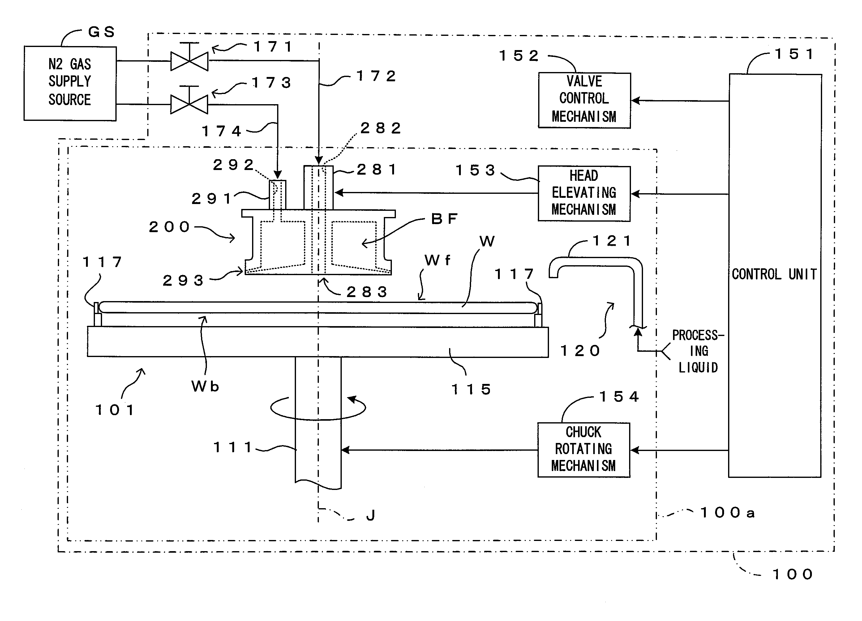
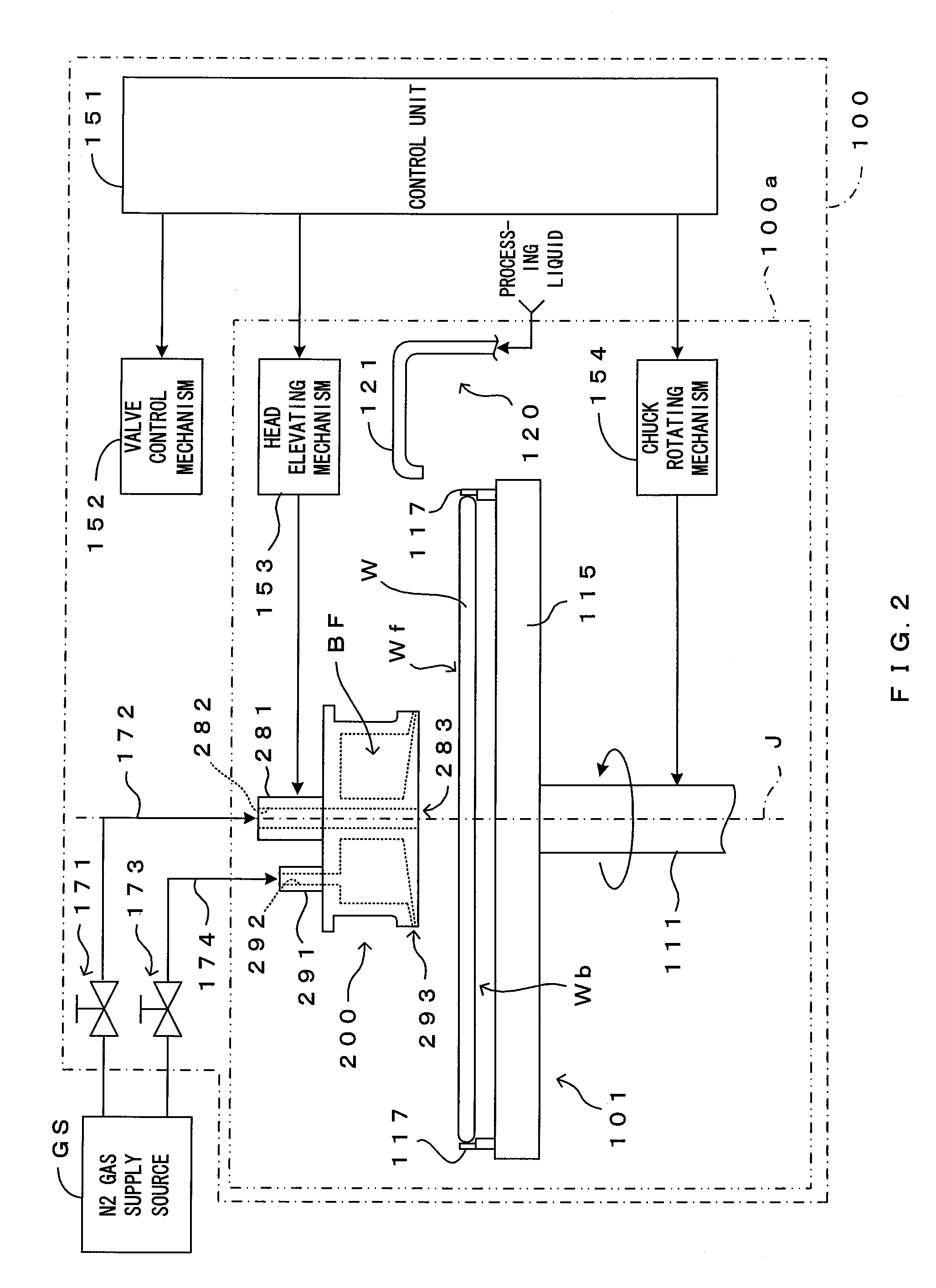
[0029]FIG. 2 is a diagram showing a first embodiment of a substrate processing unit according to the invention. This substrate processing unit 100 is a substrate processing unit of the single wafer type which is used in cleaning processing which is for removing undesired substance adhering to a surface Wf of a substrate W such as a semiconductor wafer. To be more specific, this is a processing unit in which after chemical processing with a chemical solution of a hydrofluoric acid or the like and rinsing processing with a rinsing liquid such as purified water or DIW (deionized water) are performed to the substrate surface Wf, the substrate surface Wf which is wet with the rinsing liquid is dried. Meanwhile, in this embodiment, the substrate surface Wf is a pattern-formed surface on which a device pattern is formed.

[0030]The substrate processing unit 100 comprises a spin chuck 101 which holds and rotates the substrate W approximately horizontally in a condition that the surface Wf is ...

second embodiment

[0058]Next, a second embodiment of the processing unit as the substrate processing apparatus according to the invention is described. This embodiment differs from the first embodiment in additionally including a nozzle for supplying the processing liquid to the gas injection head. Except this point, the basic apparatus construction is the same as in the first embodiment. Accordingly, in the following description, the same construction as in the first embodiment is not described by being identified by the same reference numerals and characteristic parts of this embodiment are intensively described.

[0059]FIG. 7 is a diagram showing the second embodiment of the processing unit according to the invention. In this embodiment, a gas injection head 300 is arranged above a substantial center of a substrate W held by a spin chuck 101. In the gas injection head 300, identified by 382, 383, 392 and 393 are respectively constructions corresponding to the gas supply passage 282, the gas discharg...


PUM

PropertyMeasurementUnit
distanceaaaaaaaaaa
thicknessaaaaaaaaaa
outer diameteraaaaaaaaaa

Abstract

A gas injection head 200 is provided above a substantial center of a substrate W. Nitrogen gas introduced from a gas feed port 291 is injected from a slit-shaped injection port 293 via an internal buffer space BF. In this way, a radial gas flow substantially isotropic in a horizontal direction while having an injection direction restricted in a vertical direction is generated above the substrate. Thus, dust D, mist M and the like around the substrate are blown off in outward directions and do not adhere to the substrate W. The gas injection head 200 can be made smaller than the diameter of the substrate W and needs to be neither retracted from the substrate surface nor rotated, wherefore an apparatus can be miniaturized.

Description

CROSS REFERENCE TO RELATED APPLICATION[0001]The disclosure of Japanese Patent Application No.2007-282961 filed on Oct. 31, 2007 including specification, drawings and claims is incorporated herein by reference in its entirety.BACKGROUND OF THE INVENTION[0002]1. Field of the Invention[0003]The invention relates to a substrate processing apparatus and a substrate processing method for applying a specified processing with a substrate substantially horizontally held. Here, substrates to be processed include semiconductor wafers, glass substrates for photomasks, glass substrates for liquid crystal displays, glass substrates for plasma displays, substrates for FEDs (Field Emission Displays), substrates for optical discs, substrates for magnetic discs and substrates for magneto-optical discs. The processings to be applied to the substrate include a development processing, an etching processing, a cleaning process, a rinsing processing and a drying processing.[0004]2. Description of the Rela...

Claims


Application Information

Patent Timeline
Patent Type & Authority Applications(United States)
IPC IPC(8): C23C16/00
CPCH01L21/67051H01L21/02H01L21/205H01L21/3065H01L21/50
Inventor MIYA, KATSUHIKO
Owner DAINIPPON SCREEN MTG CO LTD
Why Eureka
Try Eureka