Projector

a projector and projector technology, applied in the field of projectors, can solve the problems of insufficient heat-radiation performance, reduced reliability, increased heat-generation density, etc., and achieve the effect of preventing overheating

Inactive Publication Date: 2010-10-05
COLUMBIA PEAK VENTURES LLC
View PDF6 Cites 8 Cited by
  • Summary
  • Abstract
  • Description
  • Claims
  • Application Information

AI Technical Summary

Benefits of technology

[0015]An advantage of some aspects of the invention is to provide a projector that has sufficient heat-radiating performance, is small and thin, and has excellent portability.

Problems solved by technology

Against this background, since high-luminance light is concentrated in a small liquid crystal light valve, there are problems in that heat-generation density is increased and reliability is reduced.
However, in the above described patent document, although the radiator is arranged at a position separated from the casing above or below the projector main unit, the heat-radiation performance is still insufficient.
In particular, when the projector is miniaturized, the heat-radiation performance is insufficient; whereas increasing the size of the heat-radiating plate in order to enhance the cooling performance will prevent the miniaturization of device and obstruct its portability.
If this opening is left open during use, dust, dirt, or the like will infiltrate, which is undesirable.

Method used


Image

  • Projector
  • Projector
  • Projector

Examples


first embodiment

[0090]A first embodiment of the invention will be explained with reference to FIGS. 1 to 5.

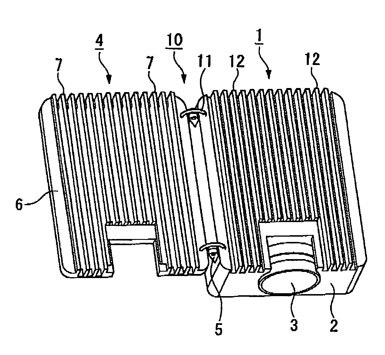
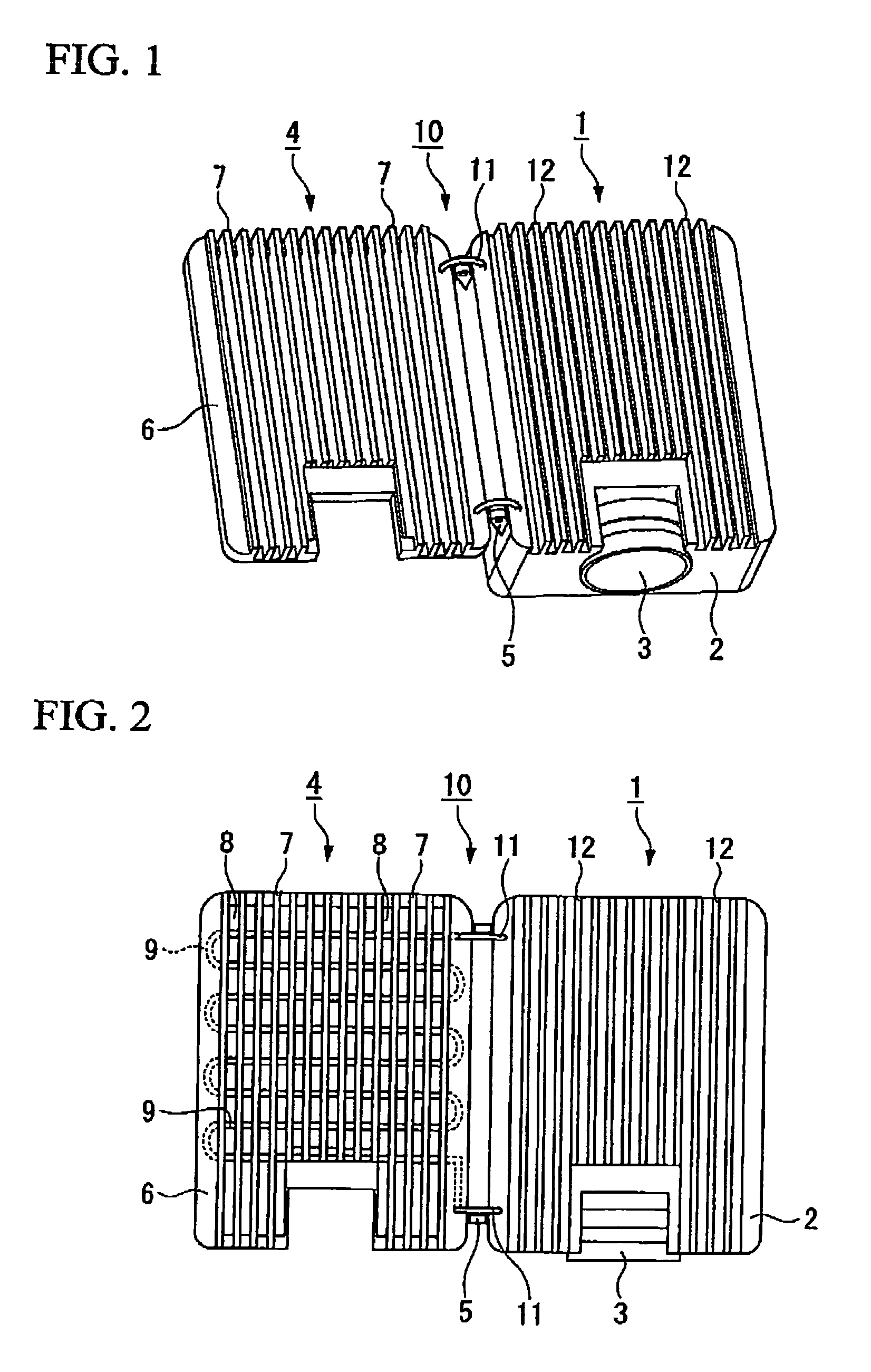
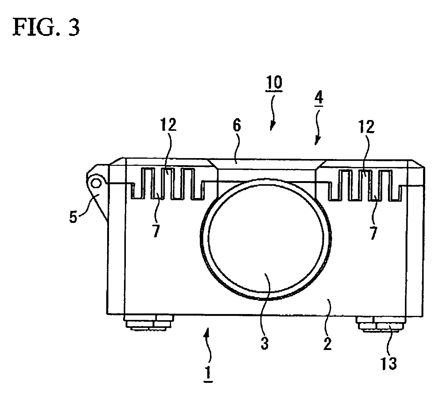
[0091]FIG. 1 is a perspective view of a deployed state of a radiator of a projector according to a first embodiment of the invention, FIG. 2 is a plan view of the same, FIG. 3 is a front view of an accommodated state of the radiator of the same projector, FIG. 4 is a basic internal configuration diagram of a projector, FIG. 5 is a block diagram relating to accommodating and deploying a radiator.

[0092]In the following drawings, dimensions are differed to facilitate recognition of the constituent parts.

[0093]As shown in FIGS. 1 and 2, a projector 10 of this embodiment includes a projector main unit 1 having a casing 2 in which various components are accommodated, a projection lens 3 exposed at a front face, and a deployable radiator 4 which is provided on a top face of the projector main unit 1 and can rotate with respect to the projector main unit 1.

[0094]Hinge 5 joins the projector main unit 1...

first modified example

[0145]The configuration can include a deployment detector detecting whether the radiator is deployed, and an illuminance controller reducing the illuminance of light from the projector main unit when the deployment detector detects that the radiator is not deployed.

[0146]The deployment detector can be configured by providing a photo-sensor, a potentiometer, or the like in the radiator and at the hinge portions.

[0147]The illuminance controller can include, for example, a lamp drive section controlling the light quantity of the lamp by controlling the current supplied to the lamp.

[0148]As shown in FIG. 6, a deployment detector 25 detects the state of the radiator 4, when the deployment detector 25 detects that the radiator 4 is not deployed, a detection signal indicating that fact input to the controller 21.

[0149]The controller 21 outputs a drive signal indicating that the light quantity should be reduced to a lamp drive section 26, and the lamp drive section drives a lamp 416.

[0150]C...

second modified example

[0152]The configuration can include a deployment detector detecting whether the radiator has deployed, and a power control unit making it impossible to inject power to the projector main unit when the deployment detector detects that the radiator is not deployed.

[0153]As described in the first modified example, the deployment detector can be configured by providing a photo-sensor, a potentiometer, or the like in the radiator and at the hinge portions.

[0154]The power controller need only include a power drive section controlling power.

[0155]As shown in FIG. 7, the deployment detector 25 detects the state of the radiator 4, and when the deployment detector 25 detects that the radiator 4 is not deployed, a detection signal indicating that fact input to the controller 21.

[0156]The controller 21 outputs a drive signal to a power drive section 27, and the power drive section 27 controls power 28 such that it is not injected even if a power button is pressed.

[0157]As a result, it is possib...


PUM


Abstract

A projector includes: a casing having a surface; a cooling medium flowpath provided inside the casing, through which a cooling medium is allowed to flow; and a radiator in which a part of the cooling medium flowpath is arranged, the radiator being deployable by rotating with respect to the casing, and adapted to be accommodated in the casing and along the surface of the casing.

Description

CROSS-REFERENCE TO RELATED APPLICATION[0001]This application claims priority from Japanese Patent Application No. 2005-308286, filed Oct. 24, 2005, the contents of which are incorporated herein by reference.BACKGROUND[0002]1. Technical Field[0003]The present invention relates to a projector.[0004]2. Related Art[0005]Recently in the field of projectors, in addition to projectors for commercial use during conferences, presentations, or the like, projectors for household use are also becoming popular.[0006]To accommodate these changing applications, small, thin and highly portable projectors are developed.[0007]Liquid crystal light valves used in projectors of this type are much smaller than conventional ones.[0008]Since a bright image is required for display, the light source luminance is increased.[0009]Against this background, since high-luminance light is concentrated in a small liquid crystal light valve, there are problems in that heat-generation density is increased and reliabil...

Claims


Application Information

Patent Timeline
Patent Type & Authority Patents(United States)
IPC IPC(8): G03B21/16
CPCG03B21/16
Inventor ZAKOJI, MAKOTOSETO, TAKESHIEGAWA, AKIRATAKAGI, KUNIHIKO
Owner COLUMBIA PEAK VENTURES LLC
Why Eureka
Try Eureka