Projector
- Summary
- Abstract
- Description
- Claims
- Application Information
AI Technical Summary
Benefits of technology
Problems solved by technology
Method used
Image
Examples
first embodiment
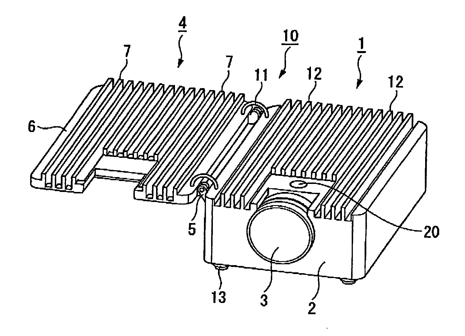
[0090] A first embodiment of the invention will be explained with reference to FIGS. 1 to 5.
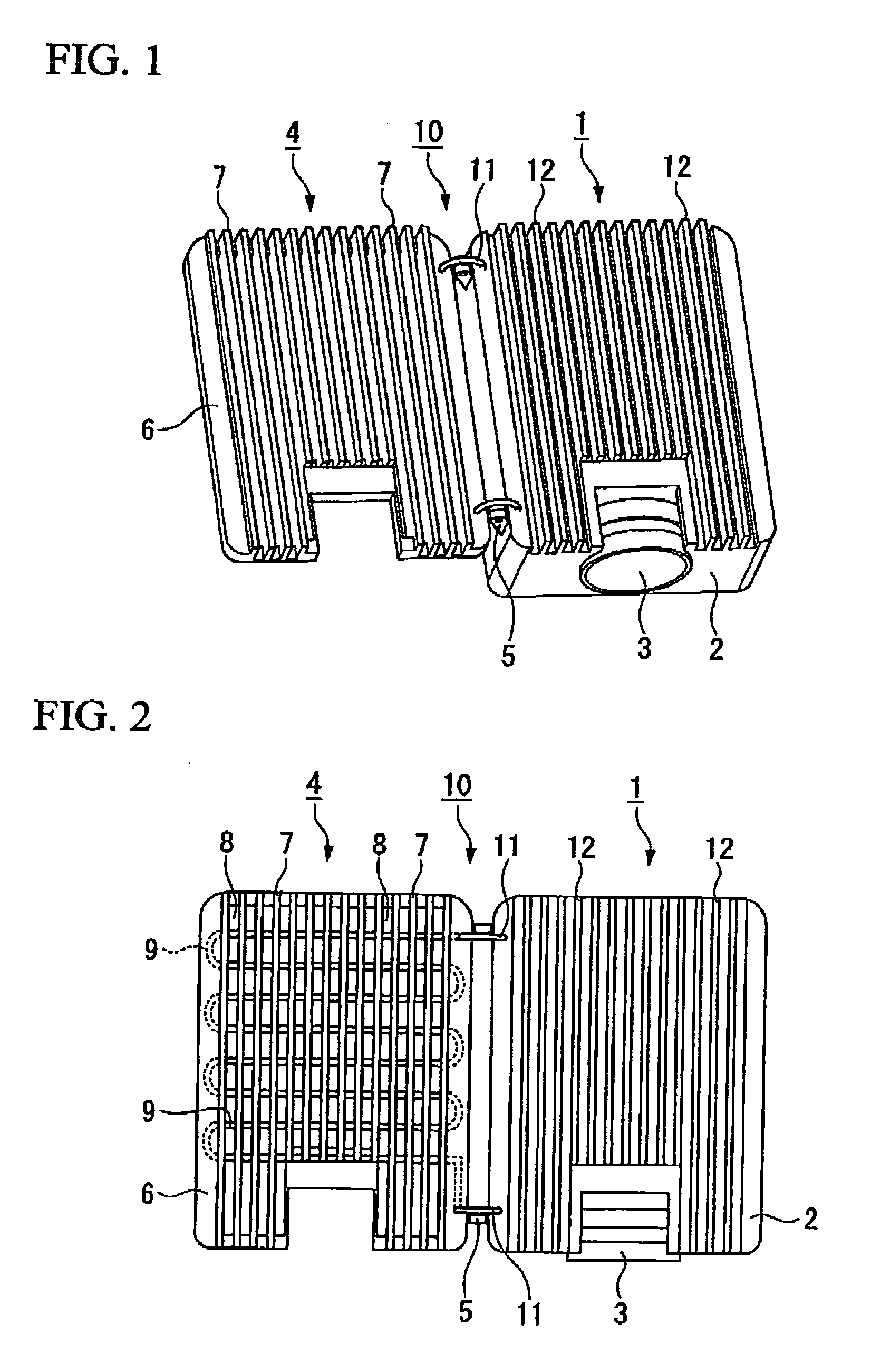
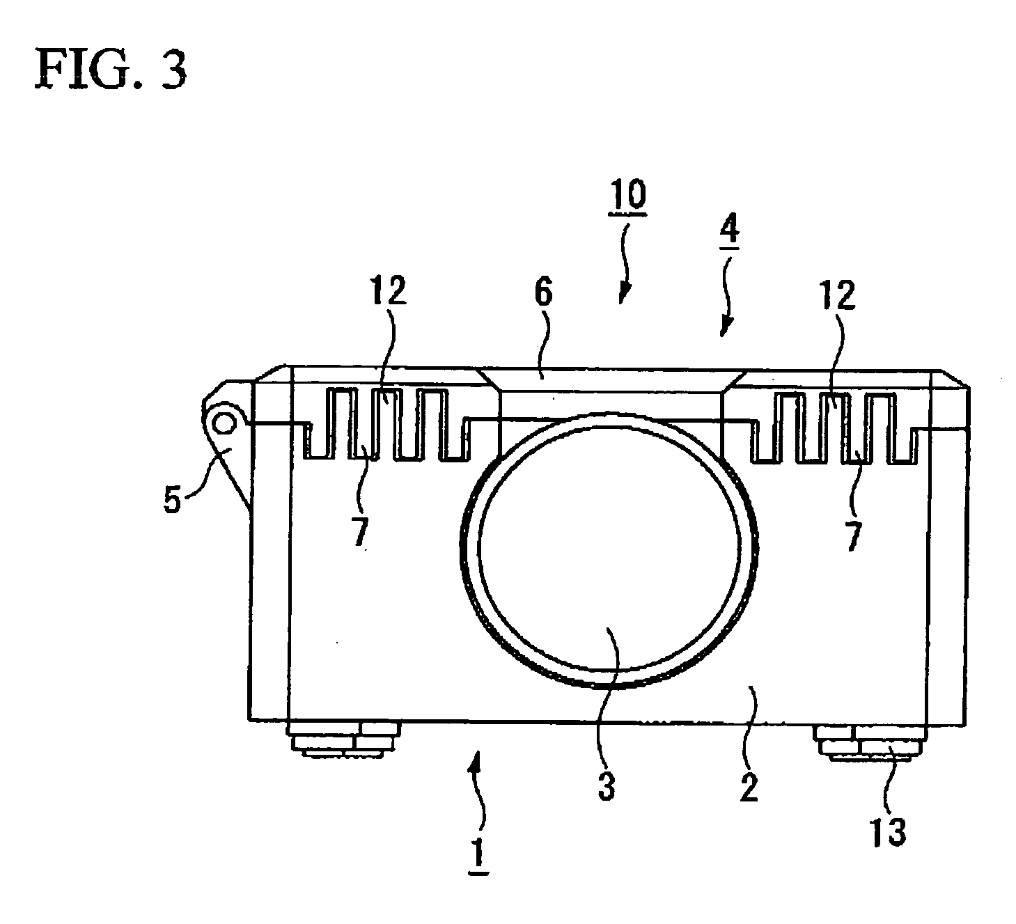
[0091]FIG. 1 is a perspective view of a deployed state of a radiator of a projector according to a first embodiment of the invention, FIG. 2 is a plan view of the same, FIG. 3 is a front view of an accommodated state of the radiator of the same projector, FIG. 4 is a basic internal configuration diagram of a projector, FIG. 5 is a block diagram relating to accommodating and deploying a radiator.
[0092] In the following drawings, dimensions are differed to facilitate recognition of the constituent parts.
[0093] As shown in FIGS. 1 and 2, a projector 10 of this embodiment includes a projector main unit 1 having a casing 2 in which various components are accommodated, a projection lens 3 exposed at a front face, and a deployable radiator 4 which is provided on a top face of the projector main unit 1 and can rotate with respect to the projector main unit 1.
[0094] Hinge 5 joins the projector mai...
first modified example
[0145] The configuration can include a deployment detector detecting whether the radiator is deployed, and an illuminance controller reducing the illuminance of light from the projector main unit when the deployment detector detects that the radiator is not deployed.
[0146] The deployment detector can be configured by providing a photo-sensor, a potentiometer, or the like in the radiator and at the hinge portions.
[0147] The illuminance controller can include, for example, a lamp drive section controlling the light quantity of the lamp by controlling the current supplied to the lamp.
[0148] As shown in FIG. 6, a deployment detector 25 detects the state of the radiator 4, when the deployment detector 25 detects that the radiator 4 is not deployed, a detection signal indicating that fact input to the controller 21.
[0149] The controller 21 outputs a drive signal indicating that the light quantity should be reduced to a lamp drive section 26, and the lamp drive section drives a lamp 41...
second modified example
[0152] The configuration can include a deployment detector detecting whether the radiator has deployed, and a power control unit making it impossible to inject power to the projector main unit when the deployment detector detects that the radiator is not deployed.
[0153] As described in the first modified example, the deployment detector can be configured by providing a photo-sensor, a potentiometer, or the like in the radiator and at the hinge portions.
[0154] The power controller need only include a power drive section controlling power.
[0155] As shown in FIG. 7, the deployment detector 25 detects the state of the radiator 4, and when the deployment detector 25 detects that the radiator 4 is not deployed, a detection signal indicating that fact input to the controller 21.
[0156] The controller 21 outputs a drive signal to a power drive section 27, and the power drive section 27 controls power 28 such that it is not injected even if a power button is pressed.
[0157] As a result, i...
PUM
 Abstract
Description
Claims
Application Information
 - R&D
- Intellectual Property
- Life Sciences
- Materials
- Tech Scout
- Unparalleled Data Quality
- Higher Quality Content
- 60% Fewer Hallucinations
Browse by: Latest US Patents, China's latest patents, Technical Efficacy Thesaurus, Application Domain, Technology Topic, Popular Technical Reports.
© 2025 PatSnap. All rights reserved.Legal|Privacy policy|Modern Slavery Act Transparency Statement|Sitemap|About US| Contact US: help@patsnap.com


