Plug locking assembly and system

a technology of locking assembly and plug, which is applied in the directions of locking device, coupling device connection, transportation and packaging, etc., can solve the problem of unwanted removal of the plug from the jack

Active Publication Date: 2010-10-05
PANDUIT
View PDF33 Cites 15 Cited by
  • Summary
  • Abstract
  • Description
  • Claims
  • Application Information

AI Technical Summary

Benefits of technology

[0005]In one aspect, a plug locking assembly comprises a cover and a latch support surface associated with the cover. The cover comprises an opening for receiving and holding a plug comprising a latch. The latch support surface is positionable to underlie the latch of the plug when the plug is positioned within the opening of the cover, thereby resisting depression of the latch.
[0008]The plug locking assembly may comprise various other features. The cover may comprise a key receiving member for receiving a key to change the position of the latch support surface. This key receiving member may comprise a stop surface for preventing over-rotation of the key. Likewise, the cover may comprise a stop surface to prevent movement of the latch support surface in a predetermined direction. The latch support surface may be substantially planar and positioned on a rotatable cam comprising a curvilinear surface. The latch support surface may be alternatively disposed in a first position spaced apart from the latch and a second position underlying a bottom surface of the latch and in contact therewith. The rotatable cam may further comprise a slot for receiving an arm of the cam latch to allow movement of the cam. Additionally, at least one of the rotatable cam and the cam latch may further comprise a retention tab to engage a slot positioned within the cover.
[0009]In another aspect of the invention, a system for securing a plug comprising a latch in position comprises a cover comprising an opening for receiving and holding the plug, a latch support member associated with the cover and a key comprising a shaft, a key tab and a limit tab. The cover also comprises a key receiving member for receiving a key. The latch support member prevents substantial movement of the latch with the plug positioned within the cover. The key tab of the key is designed for mating with the key receiving member and the limit tab is positioned on a top surface of the shaft to prevent over-rotation of the latch Support member.

Problems solved by technology

In some cases, the latch may be accidentally depressed or unauthorized users may tamper with the latch, resulting in unwanted removal of the plug from the jack.

Method used


Image

  • Plug locking assembly and system
  • Plug locking assembly and system
  • Plug locking assembly and system

Examples


Embodiment Construction

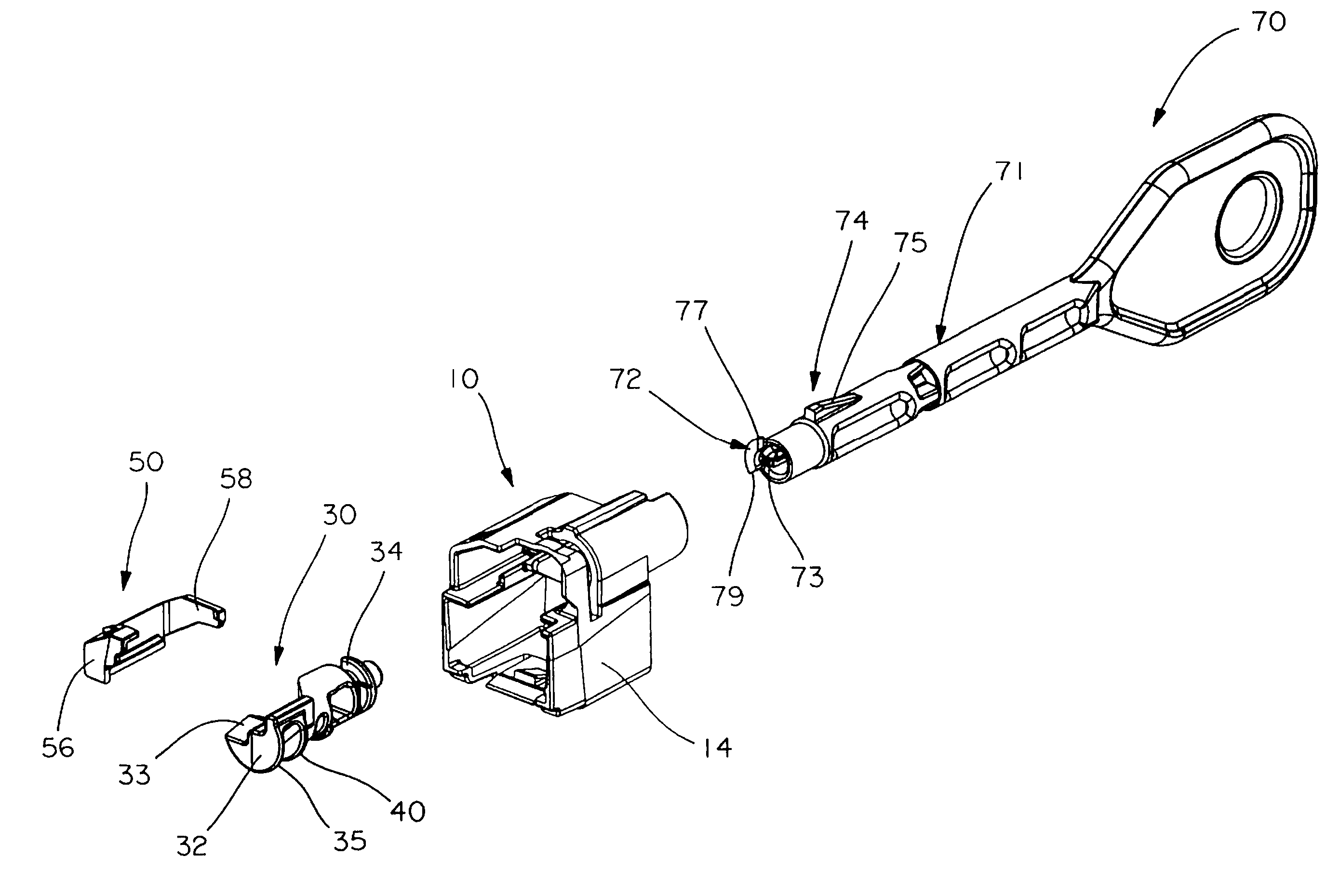
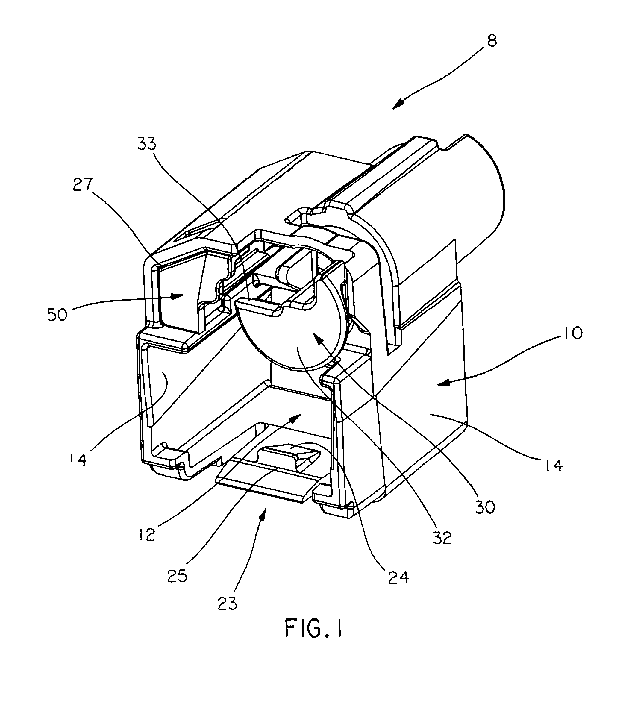
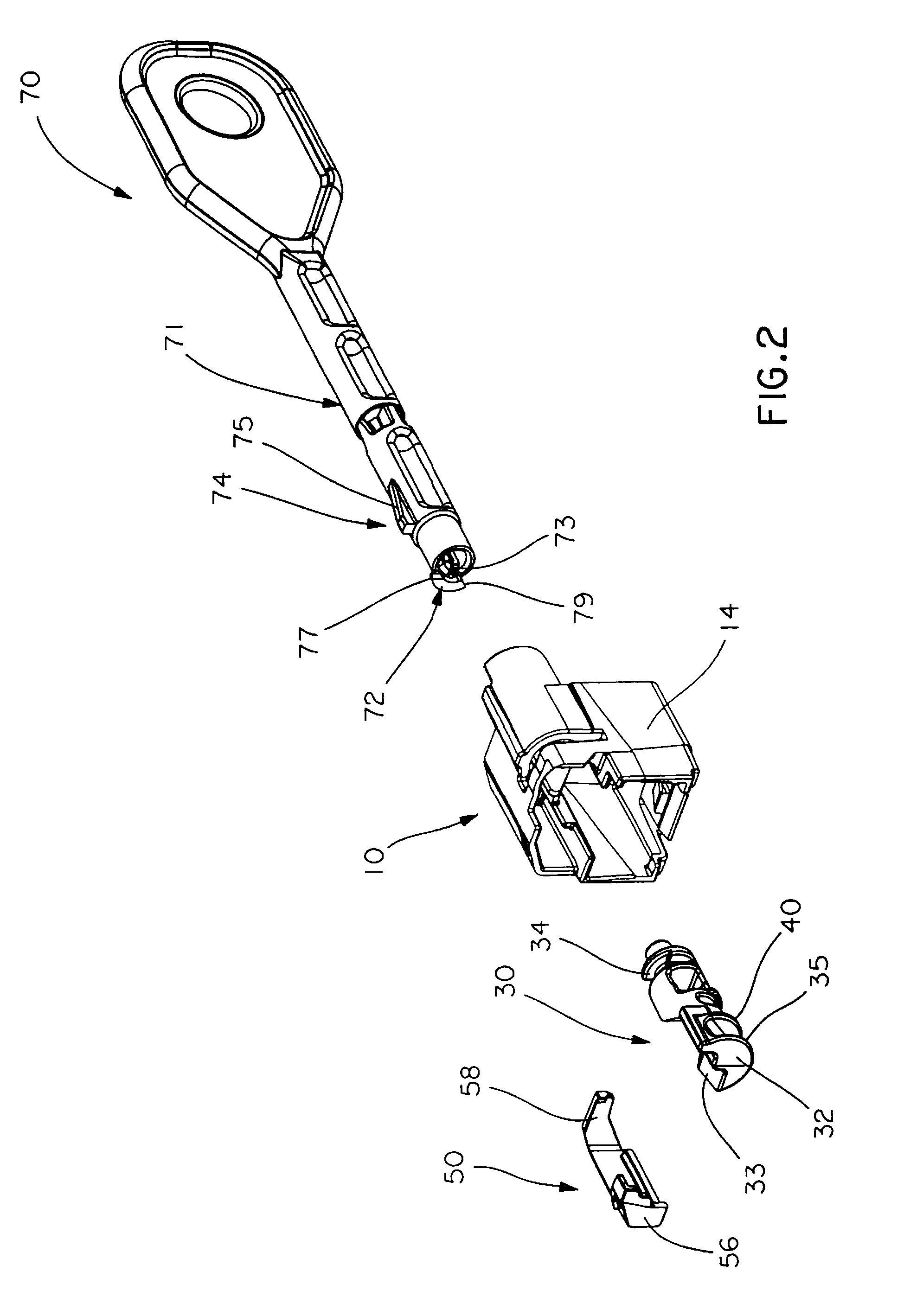
[0027]Referring to FIGS. 1-6 plug locking assembly 8 of the present invention comprises cover 10, cam 30 and cam latch 50. Locking assembly 8 may be used in connection with key 70 for rotating cam 30. The foregoing components may be made of a variety of materials, including metal and plastic, and may be constructed by methods known to those skilled in the art, including machining and injection molding.

[0028]Referring now to FIGS. 3 and 7A, cover 10 comprises opening 12, sized and shaped for receipt of a plug, opposing sidewalls 14, internal bottom surface 15, key receiving member 16 for receiving key 70, cam retention slot 26 (shown in FIG. 7A) and side stop surface 28 (also shown in FIG. 7A). Internal bottom surface 15 may comprise retaining latch 23, defined by inclined surface 24 and front stop surface 25. Retaining latch 23 secures the plug within cover 10. Key receiving member 16 may further comprise key retention lip 17, limit stops 18 and key tab slot 19. Key retention lip 17...


PUM


Abstract

A system comprises a plug locking assembly and a key. The plug locking assembly comprises a cover for receiving and holding a plug comprising a latch and a latch support surface positionable under the latch. A rotatable cam comprising a stop surface and a slot may carry the latch support surface and may interact with a cam latch comprising an arm. The arm is alternately positionable to abut the stop surface and to lie within the slot. The key may comprise a shaft, a key tab and a limit tab. The key mates with a key receiving member associated with the cover. The limit tab is positioned on a top surface of the shaft and helps prevent over-rotation of the latch support member.

Description

FIELD OF THE INVENTION[0001]This invention relates to a plug locking assembly and, more particularly, to a plug locking assembly comprising a cover and a securement feature for locking a plug into position within a jack. The invention also relates to a system comprising a plug locking assembly and a key for manipulating the plug locking assembly.BACKGROUND[0002]Modular connections often rely on the use of plugs secured within jacks. The plugs typically comprise a latch that secures the plug within the jack. The latch may be depressed to disengage the plug for easy removal from the jack, allowing disconnection of a device from a network without using tools. In some cases, the latch may be accidentally depressed or unauthorized users may tamper with the latch, resulting in unwanted removal of the plug from the jack.[0003]There is a need therefore to protect plugs and prevent their unintended disconnection from associated jacks.SUMMARY OF THE INVENTION[0004]The present invention is dir...

Claims


Application Information

Patent Timeline
Patent Type & Authority Patents(United States)
IPC IPC(8): H01R13/44
CPCH01R13/6395H01R13/6397H01R13/6272H01R24/64Y10T70/554
Inventor OBENSHAIN, MARC R.
Owner PANDUIT
Why Eureka
Try Eureka