Push-pull connector

a push-pull connector and connector technology, applied in the direction of coupling contact member, coupling device connection, coupling/disconnecting parts, etc., can solve the problem that the size of the push-pull connector may not meet certain industry standards, reduce the amount of available material for engaging the thread, and compressible material may not provide electrical shielding for the connection

Active Publication Date: 2010-10-05
TYCO ELECTRONICS LOGISTICS AG (CH)
View PDF37 Cites 107 Cited by
  • Summary
  • Abstract
  • Description
  • Claims
  • Application Information

AI Technical Summary

Benefits of technology

[0008]Optionally the sleeve member may be slidably coupled to the ring and capable of slightly rotating about the longitudinal axis when the fingers engage the wall surface of the mating connector. Also, each finger may include at least one thread element that projects radially outward. The at least one thread element may be configured to engage the mating connector. In addition, the sleeve member may be stamped and formed from a common piece of sheet material.

Problems solved by technology

The resulting size of the push-pull connector may not satisfy certain industry standards.
Also, the gaps that separate the segments reduce an amount of available material for engaging the threads.
In addition, the compressible material may not provide electrical shielding for the connection.

Method used


Image

  • Push-pull connector
  • Push-pull connector
  • Push-pull connector

Examples


Embodiment Construction

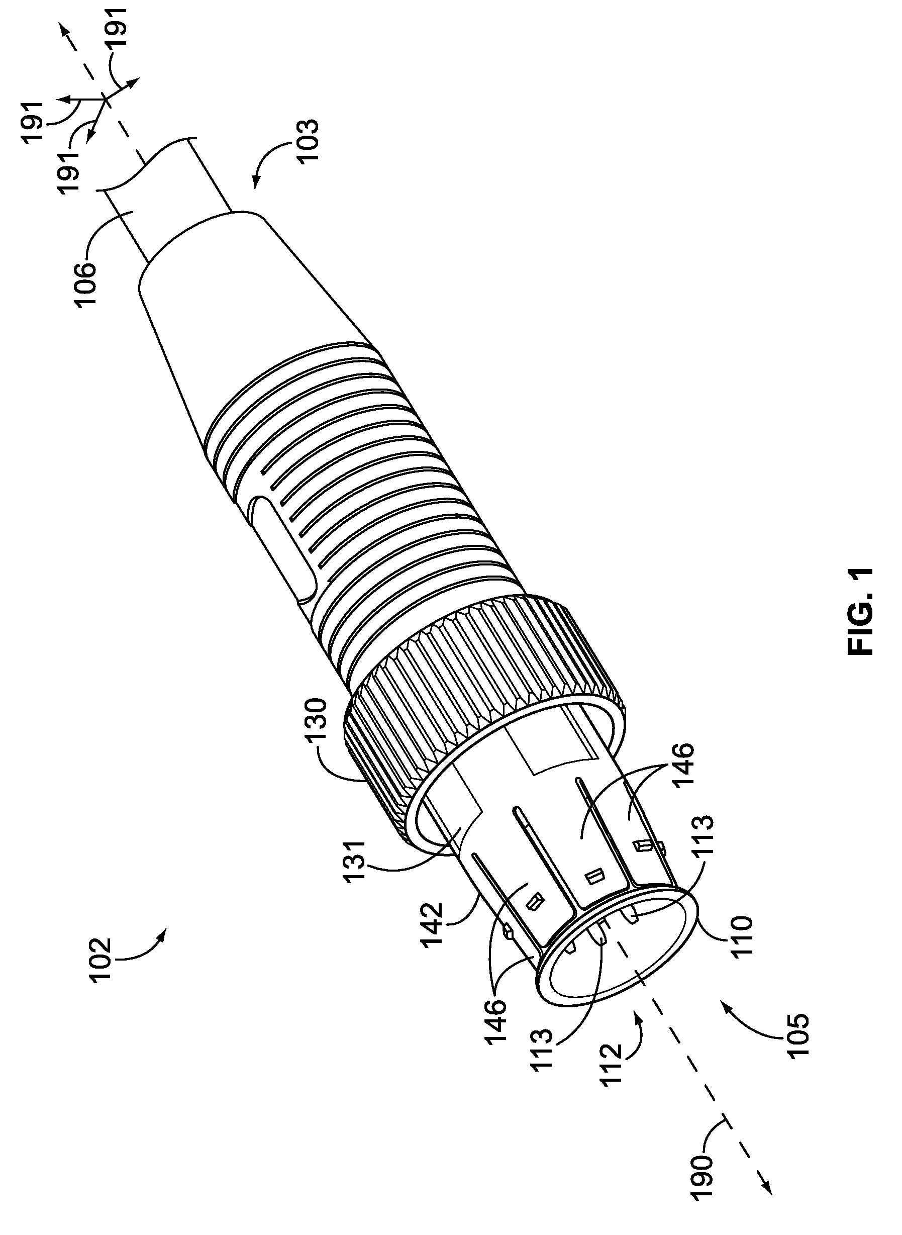
[0019]FIG. 1 is a perspective view of a connector assembly 102 formed in accordance with one embodiment. The connector assembly 102, which may also be referred to as a push-pull connector or first connector may be used to connect a cable assembly 106 to a mating connector 104 (shown in FIG. 2), which may also be referred to as a second connector. In FIG. 1, the connector assembly 102 is disengaged from the mating connector 104. The connector assembly 102 may have a substantially linear structure that extends between a loading end 103 and a mating end 105 and may extend along a longitudinal or central axis 190. The mating end 105 is configured to be inserted into a cavity 208 (shown in FIG. 2) of the mating connector 104 to establish at least one of a communicative and power connection. The communicative connection may be an electrical and / or fiber optic connection. When fully engaged, the connector assembly 102 and the mating connector 104 may form at least one of an environmental s...


PUM


Abstract

A connector assembly configured to engage a mating connector. The connector assembly includes a plug body that has loading and mating ends and a central axis extending therebetween. The mating end is configured to be inserted into a cavity of the mating connector to establish at least one of communicative and power connections. The plug body has an outer surface that surrounds and faces away from the central axis. The connector assembly also includes a ring that is slidably mounted over the plug body. The ring is configured to slide along the outer surface of the plug body in an axial direction between withdrawn and locked positions. The connector assembly also includes a sleeve member that is slidably mounted over the plug body and the ring. The sleeve member includes a plurality of fingers that extend toward the mating end and are biased toward the outer surface of the plug body. The ring is configured to engage the fingers and the fingers are configured to flex away and engage the mating connector.

Description

CROSS-REFERENCE TO RELATED APPLICATIONS[0001]The present application includes subject matter that is similar to subject matter disclosed in U.S. patent application Ser. No. 12 / 104,551, filed Apr. 17, 2008, which is incorporated by reference in the entirety. The application also includes subject matter disclosed in U.S. patent application Ser. No. 12 / 269,469, filed Nov. 12, 2008, and is incorporated by reference in the entirety.BACKGROUND OF THE INVENTION[0002]The invention relates generally to connectors, and more particularly to push-pull type connectors.[0003]Push-pull type connectors may provide a quick method for establishing a communicative and / or power connection between systems and devices. Push-pull type connectors may be female such that a mating connector is received within a cavity of the female push-pull connector. The mating connector typically has threads projecting radially outward that are engaged by the push-pull connector. Push-pull connectors may also be male wher...

Claims


Application Information

Patent Timeline
Patent Type & Authority Patents(United States)
IPC IPC(8): H01R13/627
CPCH01R13/622H01R13/639
Inventor WILLIAMS, BRIANLENKER, WILLIAMDAMODHARAN, KASTHURI
Owner TYCO ELECTRONICS LOGISTICS AG (CH)
Why Eureka
Try Eureka