
Remote monitoring of control decisions for network protectors

a network protector and remote monitoring technology, applied in the direction of transmission, circuit arrangement, instruments, etc., can solve the problems of dangerous for operators to enter the vault to obtain electrical measurements, inability to access the useful information concerning the measured conditions on either side of the network protector, and difficult to discern remotely whether the network protector relay is operating properly

Active Publication Date: 2010-10-05
DGI CREATIONS
View PDF28 Cites 36 Cited by
  • Summary
  • Abstract
  • Description
  • Claims
  • Application Information

AI Technical Summary

Problems solved by technology

The relevance of the segments to this application is that the connecting together of segments leads to the risk that during a new construction or a major repair, that a first phase of one transformer may be connected to a bus carrying the second phase of other transformers.
While these network protector relays controlled the network protector, the useful information concerning measured conditions on either side of the network protector was not available to monitoring devices that receive information about transformers via power line carrier communication.
This void in the prior art has made it difficult to discern remotely whether a network protector relay is operating properly.
Because of the high voltage and close quarters, it is potentially dangerous to have operators enter the vault to obtain electrical measurements before or after a change in the state of a network protector.
Even if the danger can be reduced sufficiently through protective equipment and special procedures, it is time consuming and inconvenient to dispatch an operator into the vault.
Given the number of network protectors in even a small distribution network, it is not desirable to incur the expense to run wiring from both sides of each network protector in a transformer vault to many various local monitoring locations outside of the transformer vaults.

Method used


Image

  • Remote monitoring of control decisions for network protectors
  • Remote monitoring of control decisions for network protectors
  • Remote monitoring of control decisions for network protectors

Examples


Embodiment Construction

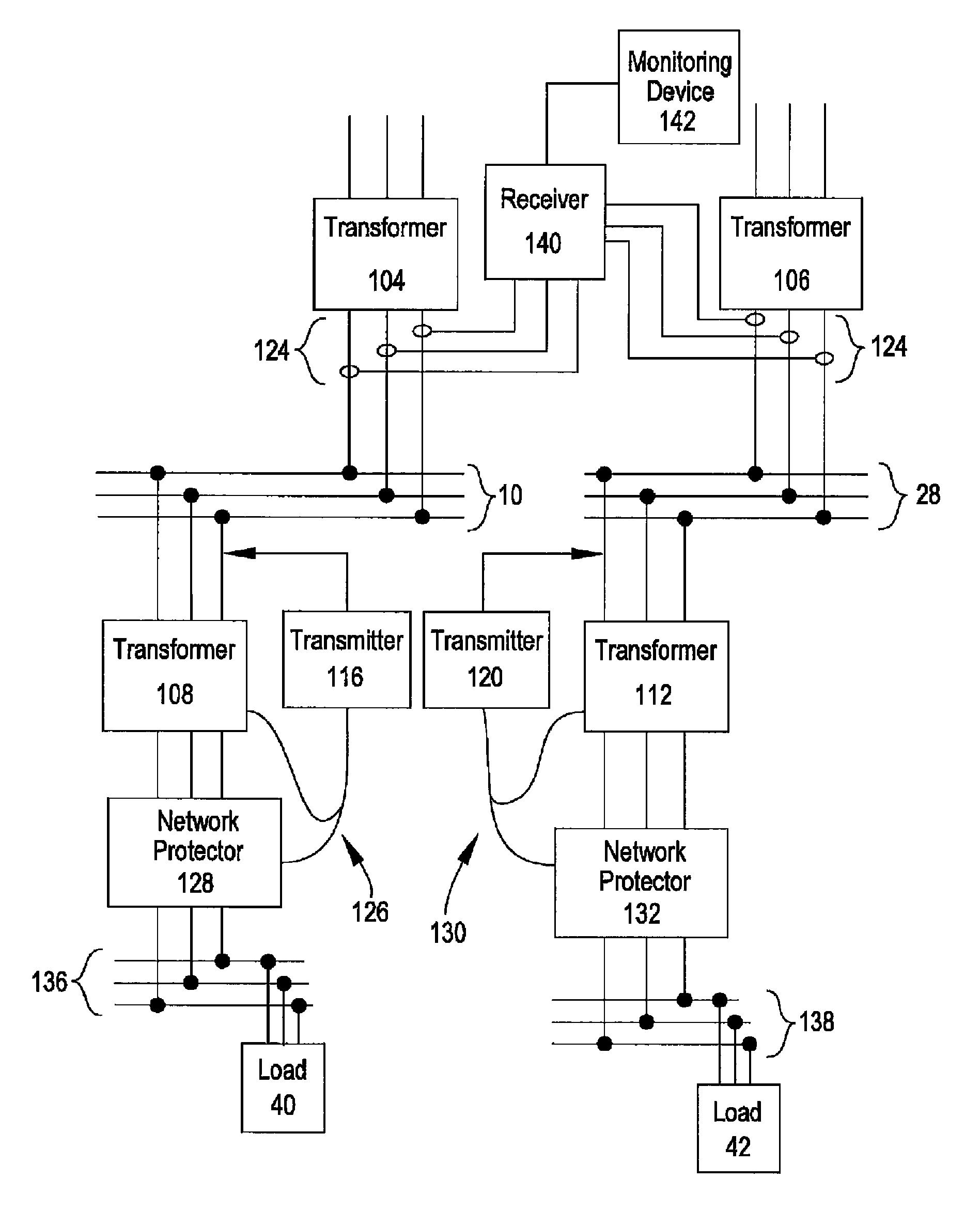
[0025]The present disclosure will now be described more fully hereinafter with reference to the accompanying drawings. The various teachings of this disclosure may, however, be embodied in many different forms and should not be construed as limited to the embodiments set forth herein; rather, these embodiments are provided so that this disclosure will be thorough and complete, and will fully convey the scope of the teachings to those skilled in the art. Like numbers refer to like elements throughout.

[0026]This application incorporates by reference U.S. patent application Ser. No. 11 / 272,632 filed Nov. 14, 2005 for Remote Monitoring of Network Protector Via Power Line Carrier which in turn claims priority and incorporates by reference U.S. Provisional Application No. 60 / 627,570 filed Nov. 12, 2004 for Remote Monitoring of Network Protector Via Power Line Carrier.

[0027]FIG. 3 shows the environment of the present disclosure in a simplified drawing in order to introduce certain relevant...


PUM


Abstract

Network protectors isolate the secondary side of a transformer from a load distribution network. It is useful to have information about the electrical parameters for the transformer and the load side of an open network protector and it is useful to have access to electrical parameters for a closed network protector. Information about a network protector can be provided to a transmitter used to convey information about the transformer associated with that network protector so that information about the network protector can be sent over power liner carrier to a centralized receiver.

Description

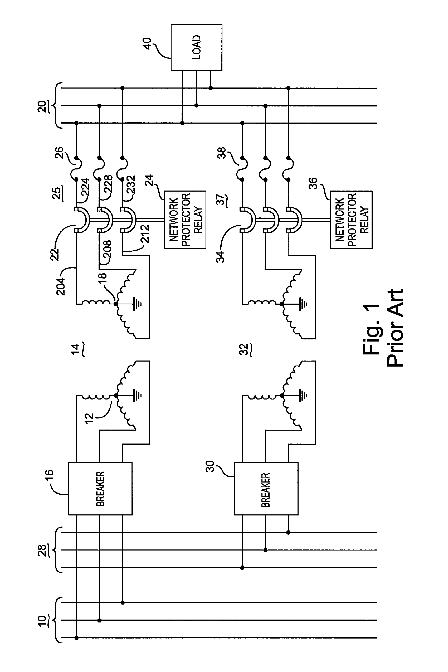
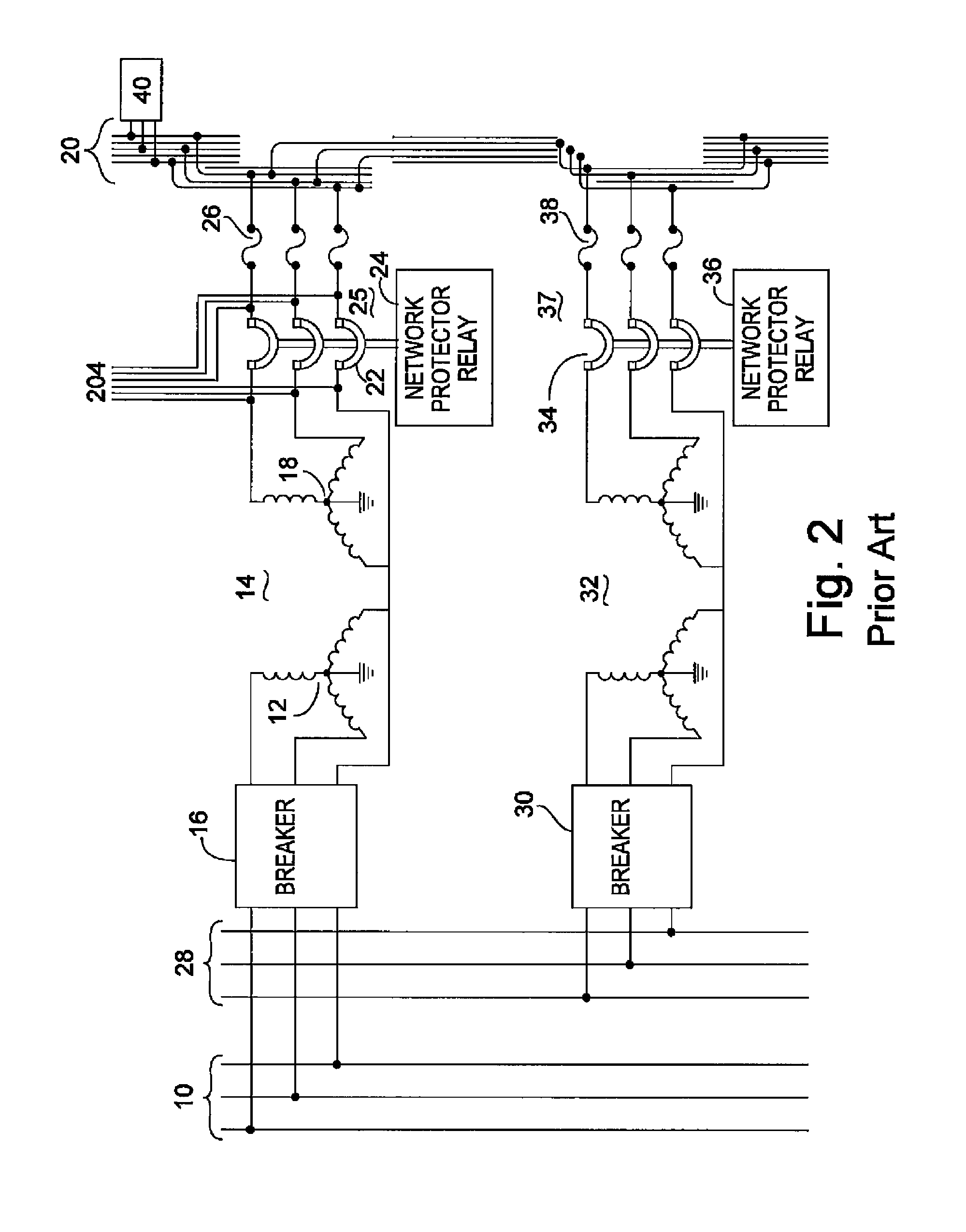
BACKGROUND[0001]1. Field of the Disclosure[0002]This disclosure for apparatus and methods for a data processing computer to receive and process information relevant to testing whether a particular piece of equipment (a network protector) located at a remote location is operating in accordance with a set of control system rules to open and close the network protector. (See for example Class 702, subclasses 183 and 286).[0003]2. Description of the Prior Art & Problems with Prior Art Solutions[0004]The prior art has evolved a series of solutions to address the needs to distribute electrical power. The solutions include the use of low voltage grid or spot networks. FIG. 1 is taken from U.S. Pat. No. 4,293,886 for Network Protector Relay where the components were introduced as follows “A typical application for a network protector relay of the type disclosed herein is shown in FIG. 1. In FIG. 1 a first substation feeder 10 is connected to a primary winding 12 of a first step down transfo...

Claims


Application Information

Patent Timeline
IPC IPC(8): H02H3/00G01R31/327
CPCG01R31/3275H02H1/0076H02H7/261
Inventor WEBER, JR., JOHN ROBERTSCHEUERMANN, CARL FRANCIS
Owner DGI CREATIONS
Learn More