Flow driven piezoelectric energy harvesting device

a piezoelectric energy harvesting and flow-driven technology, applied in the direction of generators/motors, cycle equipment, optical signals, etc., can solve the problems of limited storage life, heavy weight, limited amount of energy that can be generated during setback, and weapons that do not experience setback acceleration

Inactive Publication Date: 2010-10-05
THE UNITED STATES OF AMERICA AS REPRESENTED BY THE SECRETARY OF THE NAVY
View PDF19 Cites 39 Cited by
  • Summary
  • Abstract
  • Description
  • Claims
  • Application Information

AI Technical Summary

Problems solved by technology

Batteries, however, are heavy, expensive and have a limited shelf life.
Because of the relatively short duration of setback acceleration, the amount of energy that can be generated during setback is limited.
In addition, some weapons do not experience setback acceleration.

Method used


Image

  • Flow driven piezoelectric energy harvesting device
  • Flow driven piezoelectric energy harvesting device

Examples


Embodiment Construction

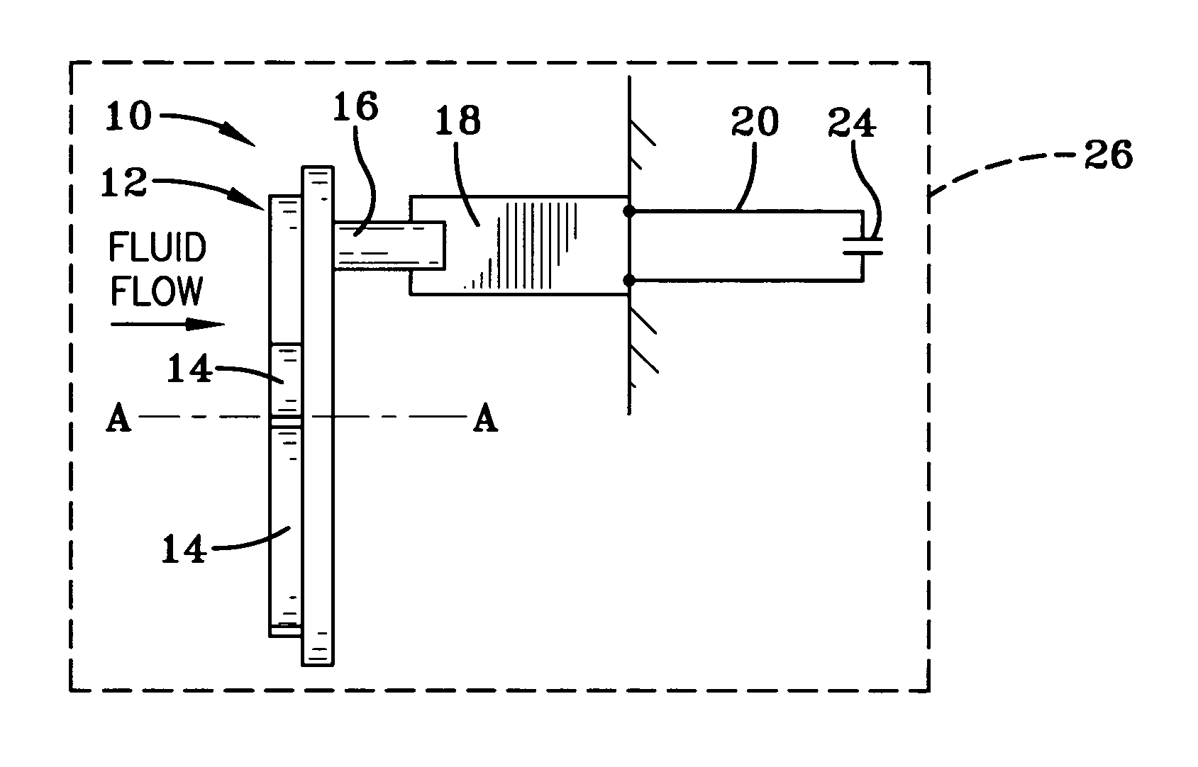
[0016]The invention includes an apparatus and method for generating electricity from fluid flow. The fluid may be a gas or liquid. One application for the invention is an energy supply for a weapon. When the weapon is airborne, the fluid flow that powers the apparatus is the air flow around the weapon. The electricity that is generated may be used as it is generated or stored for later use. In a weapon, the electricity is generally used to initiate an explosive fire train.

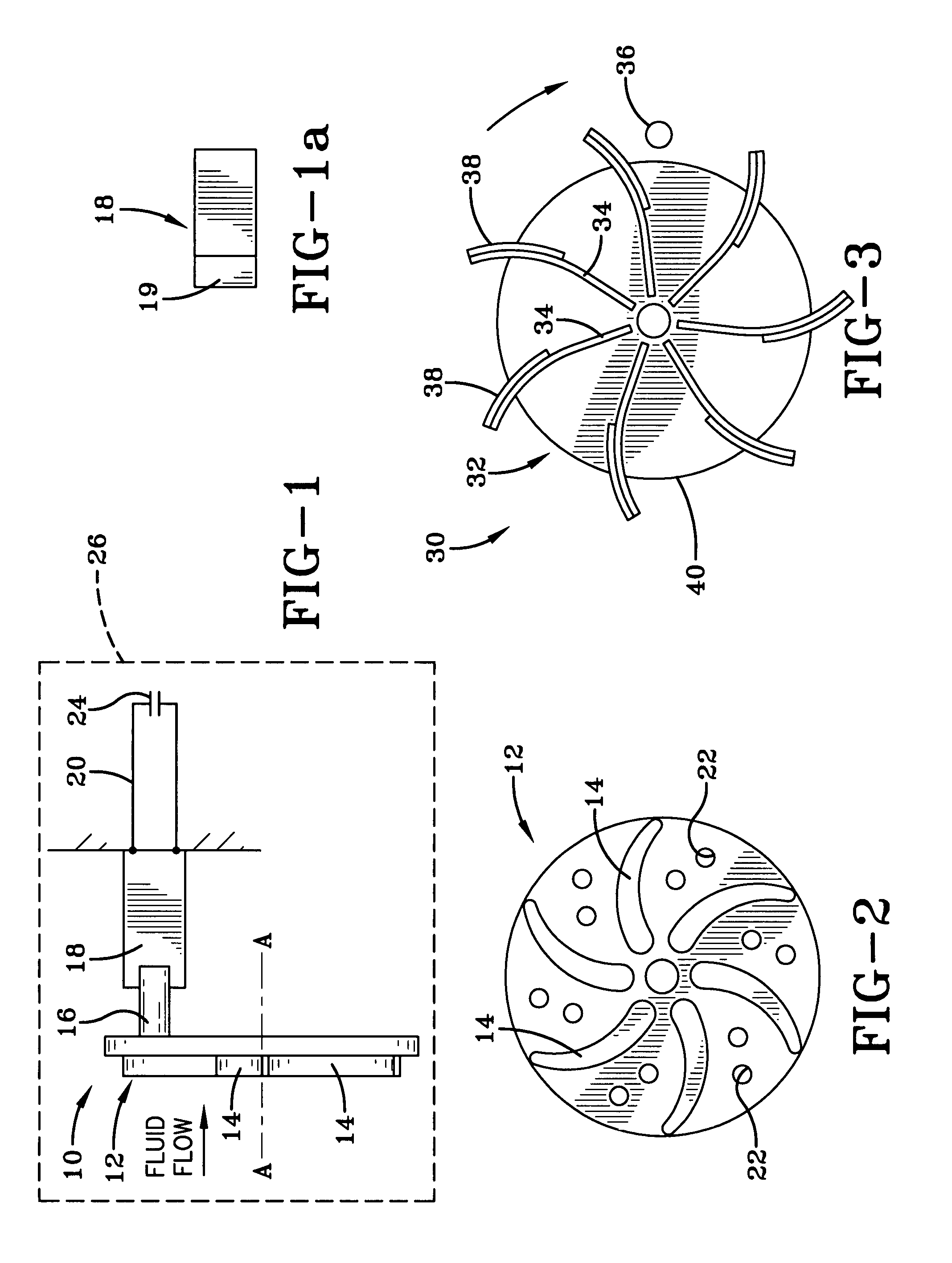
[0017]FIG. 1 shows one embodiment of an electricity generating apparatus 10 in accordance with the invention. Apparatus 10 includes a fluid-flow driven impeller 12 having a plurality of vanes 14. The impeller 12 may be axial or radial flow and rotates about axis A-A. Impeller 12 includes at least one impact arm 16. Disposed adjacent impeller 12 is at least one cantilevered beam 18. Beam 18 is disposed such that the impact arm 16 strikes the cantilevered beam 18 as the impeller 12 rotates. The cantilevered beam 18 i...


PUM


Abstract

An electrical generator includes a fluid-flow driven impeller including at least one impact arm; and at least one cantilevered beam disposed such that the impact arm strikes the cantilevered beam as the impeller rotates. The cantilevered beam at least partially includes a piezoelectric film.

Description

STATEMENT OF GOVERNMENT INTEREST[0001]The invention described herein may be manufactured and used by or for the Government of the United States of America for Governmental purposes without the payment of any royalties thereon or therefor.BACKGROUND OF THE INVENTION[0002]The invention relates in general to electric power generators and in particular to piezoelectric power generators.[0003]Many weapons require an electrical pulse to initiate their explosive fire train. The electrical pulse is typically provided by electrical energy stored in the weapon's fuze. Batteries are one method to store electrical energy. Batteries, however, are heavy, expensive and have a limited shelf life. Conventional technologies disclose the use of piezoelectric films that are strained during setback acceleration to generate electricity. Because of the relatively short duration of setback acceleration, the amount of energy that can be generated during setback is limited. In addition, some weapons do not e...

Claims


Application Information

Patent Timeline
Patent Type & Authority Patents(United States)
IPC IPC(8): H02N2/18
CPCH02N2/185H01L41/1136H10N30/306
Inventor DEEDS, MICHAELVALERIANO, VERONICALAIB, GERALDHENDERSHOT, JOHNOLSON, DAVID
Owner THE UNITED STATES OF AMERICA AS REPRESENTED BY THE SECRETARY OF THE NAVY
Why Eureka
Try Eureka