
Microphone assembly comprising magnetically activatable element for signal switching and field indication

a technology of magnetic activation and signal switching, which is applied in the direction of electronic input selection/mixing, piezoelectric/electrostrictive transducers, transducer types, etc., can solve the problems of inability to dispense with or overrule automatic switching between input signal sources, particularly troublesome for small hearing aids, etc., to improve the ability to determine or sense weak magnetic fields, increase the magnetic field, and improve the effect of detecting weak magnetic fields

Inactive Publication Date: 2010-10-05
SONION NEDERLAND
View PDF19 Cites 77 Cited by
  • Summary
  • Abstract
  • Description
  • Claims
  • Application Information

AI Technical Summary

Benefits of technology

The present invention provides a microphone assembly with a magnetically activated element that can selectively route a microphone signal or an external input signal based on the presence of a magnetic field. This element can be a reed relay, a Hall sensor, or a magnetically activatable switch. The magnetically activated element can be disposed adjacent to a microphone preamplifier on a common ceramic carrier substrate within the microphone housing. The assembly also includes a sensor for sensing the magnetic field and outputting a signal relating to the magnetic field. This sensor can be used in a hearing aid or prosthesis that includes the microphone assembly. The technical effects of the invention include improved control of the microphone signal based on the magnetic field, increased sensitivity of the magnetic field, and better detection of weak magnetic fields.

Problems solved by technology

Several drawbacks are associated with these prior art techniques.
This is particularly troublesome for small hearing aids such as ITC and CIC-type of hearing aids which are adapted for positioning partly or entirely within the user's ear canal and which therefore must posses very small dimensions.
By routing the switchable input signals through the relay switch itself, it is impossible to dispense with or overrule the automatic switching between input signal sources when a static magnetic field of some predetermined threshold value is applied to the reed relay.

Method used


Image

  • Microphone assembly comprising magnetically activatable element for signal switching and field indication
  • Microphone assembly comprising magnetically activatable element for signal switching and field indication
  • Microphone assembly comprising magnetically activatable element for signal switching and field indication

Examples


Embodiment Construction

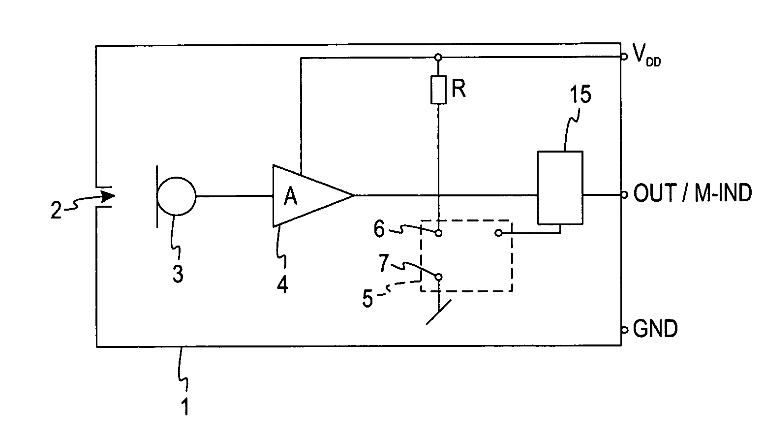
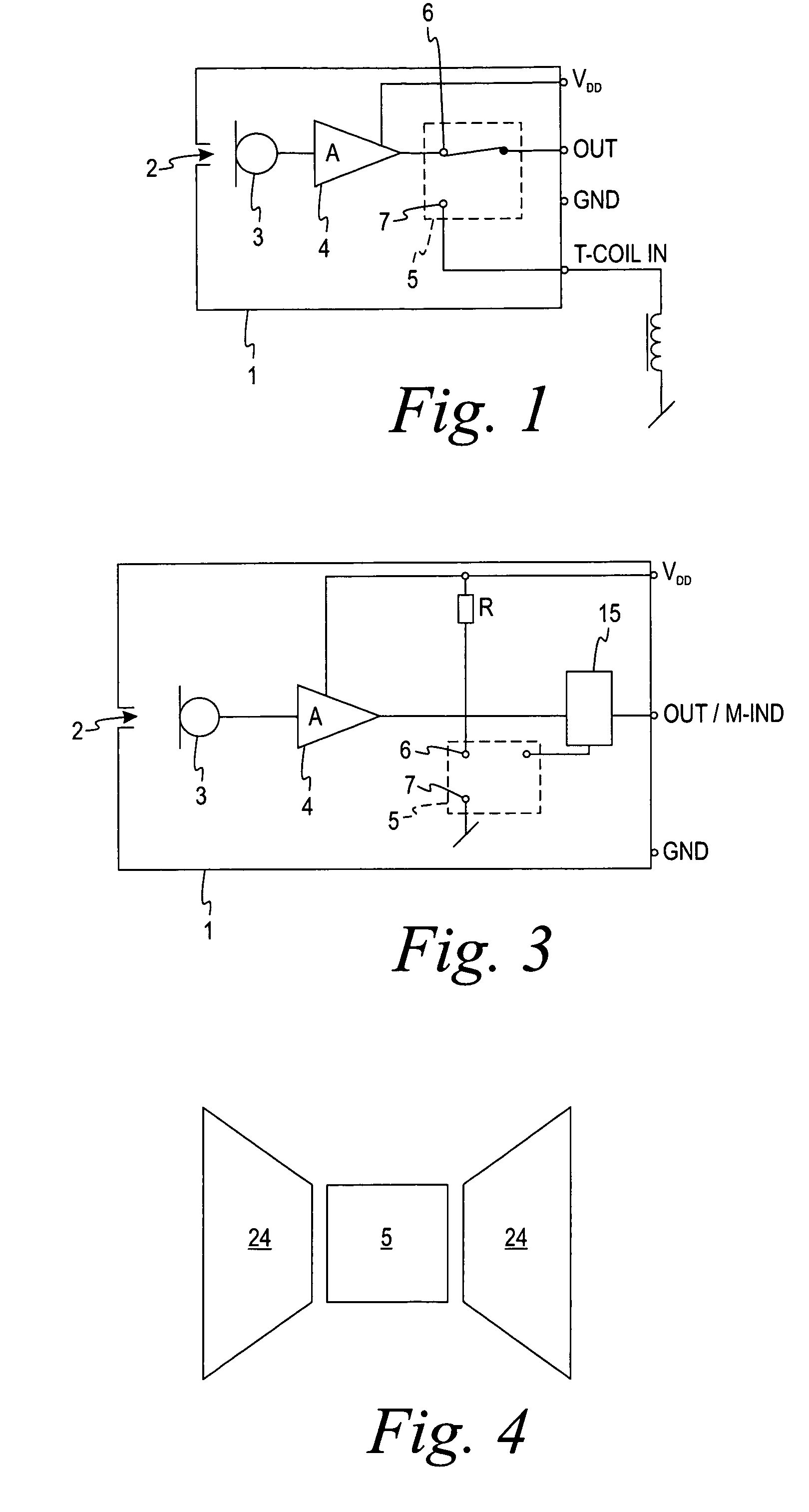
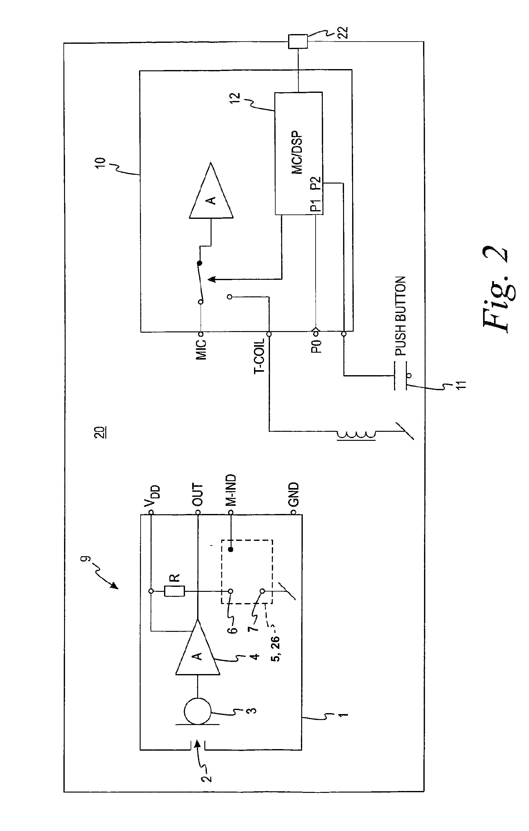
[0032]FIG. 1 shows a miniature microphone assembly suitable for use in hearing aids and that comprises an electret transducer element 3 disposed inside a microphone housing 1. The microphone housing 1 has a sound inlet port 2 for receipt of incoming sound signals and four externally accessible electrical terminals VDD, OUT, T-COIL IN and GND. A microphone preamplifier 4 is operatively coupled to the electret transducer element 3 to amplify and / or buffer signals therefrom. A micro reed relay 5 comprises first and second input terminals connected to a preamplifier output 6 and T-coil input 7, respectively and operative to selectively connect one of the preamplifier output 6 and T-coil input 7 to external output terminal OUT of the microphone assembly depending on whether a magnetic field strength acting on the micro reed relay is above or below a predetermined threshold. The preamplifier 4 and the micro reed relay 5 are mounted on common ceramic substrate (not shown) disposed inside t...


PUM


Abstract

A microphone assembly comprising a transducer for receiving sound and outputting a corresponding control signal. The assembly also comprises means for detecting a magnetic field and outputting a signal relating to the field. A hearing aid comprising the assembly has a processor receiving the control signal and selecting between the microphone signal and a signal relating to the magnetic field, such as a signal received from a telephone hand set or a telecoil.

Description

RELATED APPLICATION[0001]This application claims the benefit of U.S. Provisional Application No. 60 / 585,037, entitled “Microphone Assembly Comprising Magnetically Activated Switch For Signal And Field Indication,” filed Jul. 2, 2004.FIELD OF THE INVENTION[0002]The present invention relates to a microphone assembly comprising a magnetically activatable element arranged inside the microphone housing so as to allow automatic signal source selection between two or more signal sources. A magnetically activatable element arrangement is adapted to detect a presence of a static magnetic field from, e.g., a telephone handset loudspeaker and provide a field indicator control signal associated with the presence or absence of the telephone handset.BACKGROUND OF THE INVENTION[0003]It is well-known in the art to incorporate a reed-relay on a hearing prosthesis circuit board and be operable to switch between a telecoil input signal and a microphone input signal depending upon a field strength valu...

Claims


Application Information

Patent Timeline
Patent Type & Authority Patents(United States)
IPC IPC(8): H04R9/08
CPCH04R25/43H04R25/554H04R25/558
Inventor VAN HALTEREN, AART ZEGERSALMI, PETER
Owner SONION NEDERLAND
Learn More