Reserve tank layout structure of motorcycle

a technology for reserve tanks and motorcycles, which is applied in the field of reserve tank layout structures of motorcycles, can solve the problems of hard to secure the capacity of reserve tanks and difficult to check out the remaining amount of cooling water in the reserve tanks from an external portion of the motorcycl

Active Publication Date: 2010-10-12
KAWASAKI MOTORS LTD
View PDF8 Cites 2 Cited by
  • Summary
  • Abstract
  • Description
  • Claims
  • Application Information

AI Technical Summary

Benefits of technology

[0007]The present invention addresses the above described condition, and an object of the present invention is to provide a reserve tank layout structure of a motorcycle which can secure a capacity of the reserve tank, and allow a remaining amount of a cooling water in the reserve tank to be easily checked from an external portion of the motorcycle.
[0009]In accordance with this structure, since it is possible to increase a capacity of the reserve tank by utilizing a space in the inner peripheral side of the rope-like body of the wrapping transmission mechanism, and it is possible to arrange the reserve tank in a side portion of the motorcycle provided with the wrapping transmission mechanism, it is possible to easily check out a remaining amount of the cooling water within the reserve tank from an external portion.
[0011]In accordance with this structure, since it is possible to make the relative position of a radiator for the engine normally supported on the vehicle body frame and the reserve tank constant, it is possible to simplify a pipe arrangement structure for connecting the radiator and the reserve tank.
[0013]In accordance with this structure, since it is possible to make the relative position of the reserve tank and the rope-like body constant, it is not necessary to take into consideration a vertical movement of the rope-like body in accordance with a vertical oscillation of the swing arm, so that it is possible to further increase the capacity of the reserve tank by widely using the inner peripheral side space of the rope-like body.
[0015]In accordance with this structure, in the case that the belt transmission mechanism is used as the wrapping transmission mechanism, it is possible to enlarge a diameter of a pulley winding the belt therearound so as to widen the space in the inner peripheral side of the belt, in comparison with the case of using a chain transmission mechanism, so that it is possible to further increase the capacity of the reserve tank.

Problems solved by technology

However, since a space near the meter is narrow, it is hard to secure a capacity of the reserve tank.
However, since the reserve tank gets into an inner side of the swing arm, it is hard to check out a remaining amount of a cooling water in the reserve tank from an external portion of the motorcycle.

Method used


Image

  • Reserve tank layout structure of motorcycle
  • Reserve tank layout structure of motorcycle
  • Reserve tank layout structure of motorcycle

Examples


first embodiment

(Operation and Effect of First Embodiment)

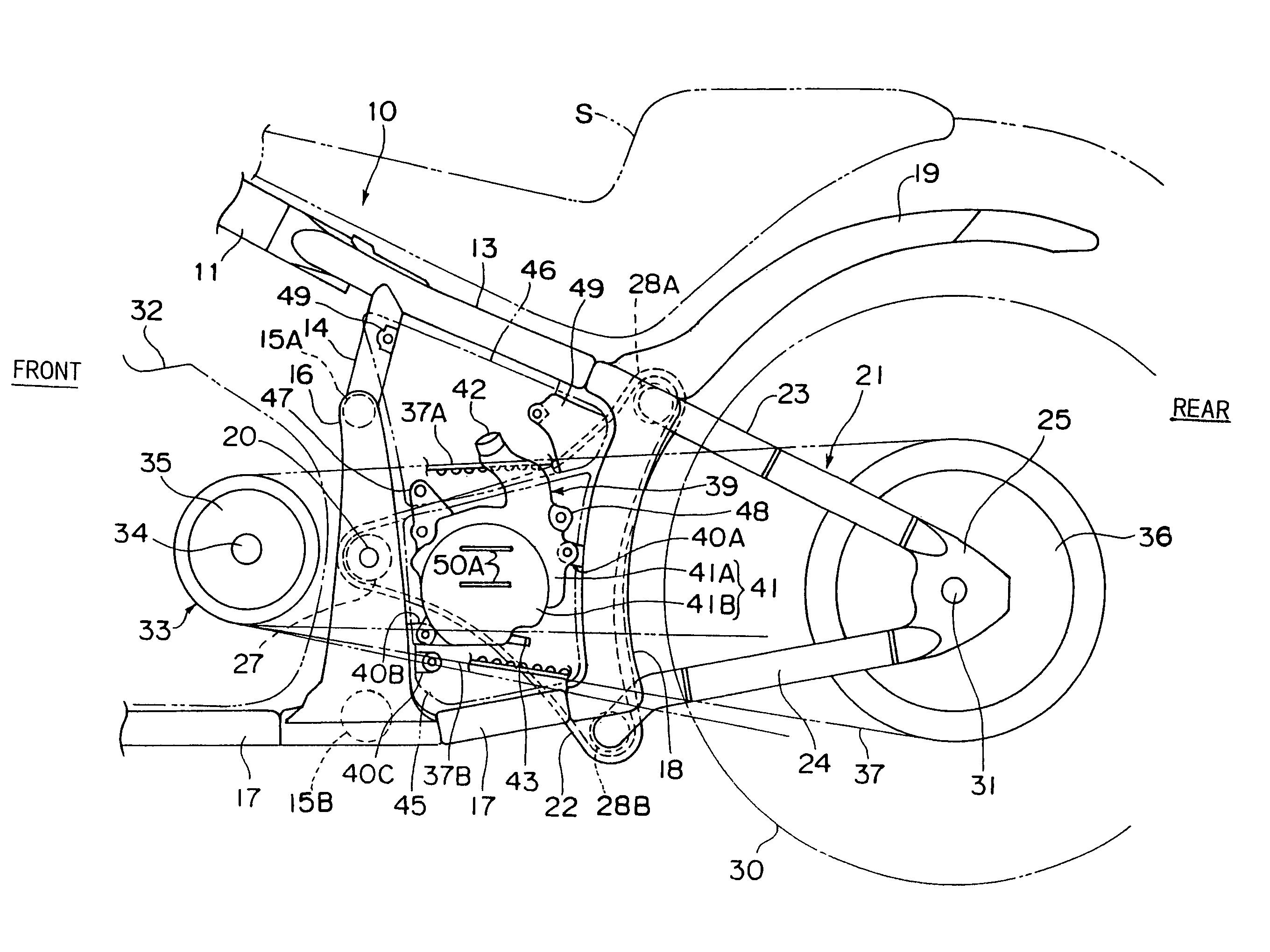
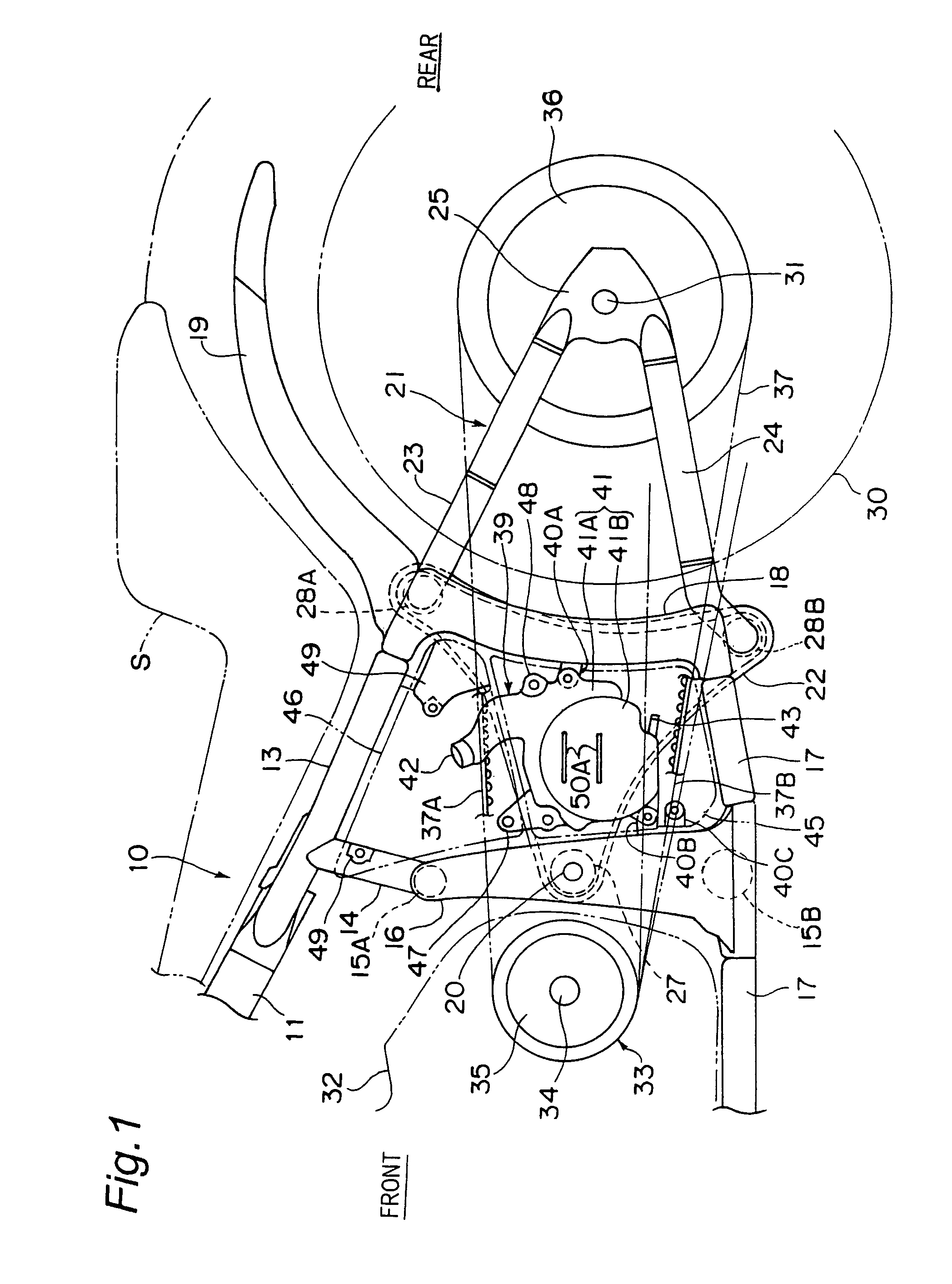
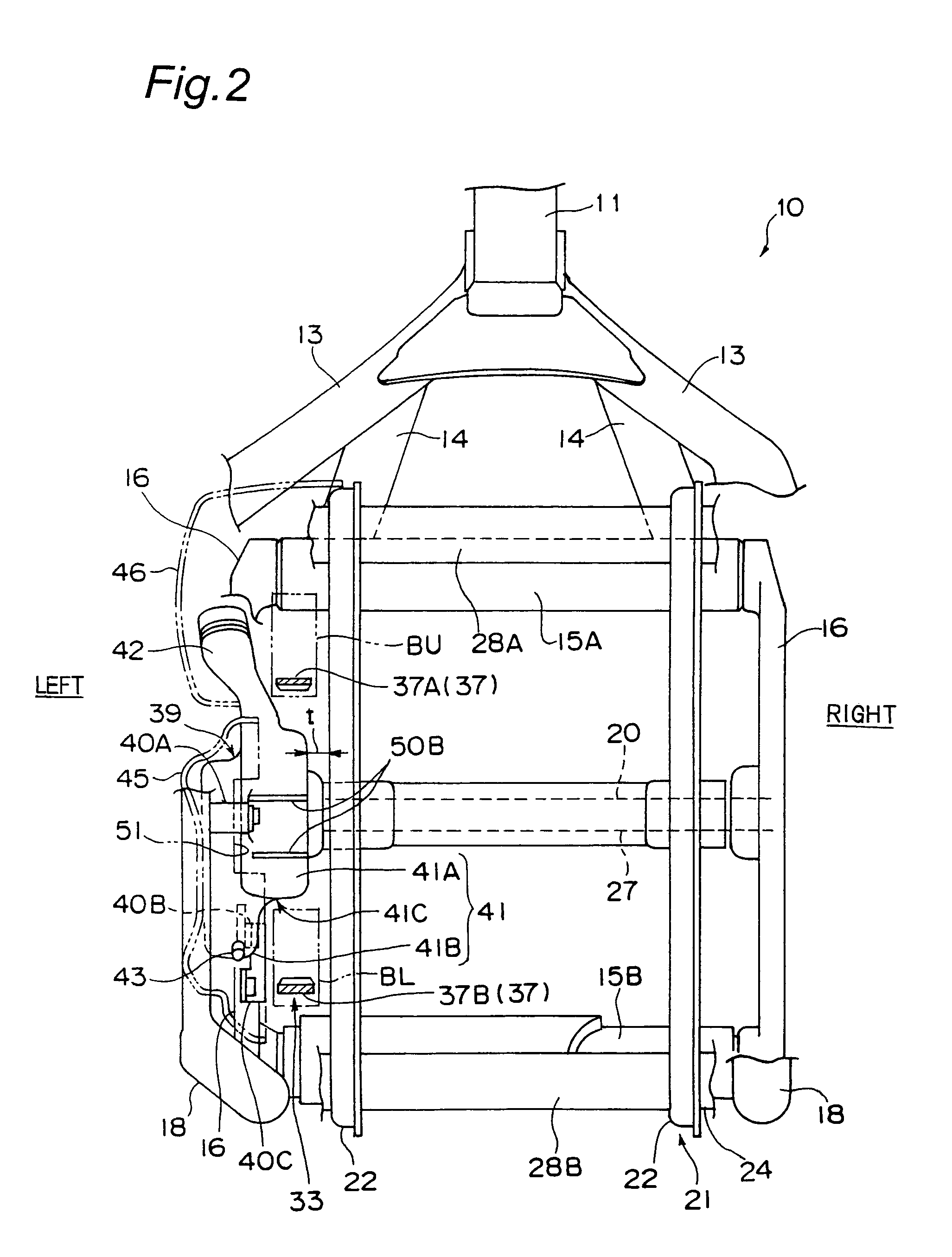
[0036]As shown in FIG. 2, since the right side portion 41A of the reserve tank 39 is arranged in the space between the upper portion 37A and lower portion 37B (the inner peripheral side) of the transmission belt 37, and the left side portion 41B is arranged outwardly of the transmission belt 37 so as to bulge downwardly from the right side portion 41A, the reserve tank can have a large capacity.

[0037]Since the belt transmission mechanism is used as the wrapping transmission mechanism 33, it is possible to make the diameters of the drive pulley 35 and the driven pulley 36 large, it is possible to form the interval between the upper portion 37A and the lower portion 37B of the transmission belt 37 wide, and it is possible to easily increase the capacity of the reserve tank 39.

[0038]As shown in FIG. 2, since the reserve tank 39 is arranged in such a manner as to cover the upper side of the lower portion 37B of the transmission belt 37, the rese...

second embodiment

[0041]FIG. 3 is a left side elevational view showing a main portion of a rear portion of a vehicle body frame, in a motorcycle in accordance with a second embodiment of the present invention, and FIG. 4 is a schematic view showing a layout of parts in the case of viewing the vehicle body frame from a back side, in the second embodiment. The present embodiment is different from the first embodiment in a point that the reserve tank 39 is attached to the swing arm 21. Since the other structures are the same as the first embodiment, a detailed description thereof will be omitted by attaching the same reference numerals.

[0042]Specifically, the reserve tank 39 is integrally provided with mounting pieces 53 protruding rearwardly and forwardly, and the mounting pieces 53 are attached to the main member 22 of the swing arm 21 by bolts or the like. As shown in FIG. 4, the main body portion 41 of the reserve tank 39 is arranged between the upper portion 37A and the lower portion 37B of the tra...


PUM


Abstract

A reserve tank layout structure of a motorcycle can secure a capacity of a reserve tank, and allow for easy checking of a remaining amount of a cooling water in the tank from the exterior. The layout structure is provided with a vehicle body frame, an engine supported by the vehicle body frame, a swing arm attached to the vehicle body frame so as to freely oscillate, a rear wheel supported by the swing arm, a wrapping transmission mechanism having an endless rope-like body wound between an output shaft of the engine and an axle of the rear wheel and transmitting power from the output shaft to the axle, and a reserve tank for storing cooling water of the engine, the reserve tank being disposed so that at least a part thereof is positioned at an inner peripheral side of the rope-like body.

Description

BACKGROUND OF THE INVENTION[0001]1. Field of the Invention[0002]The present invention relates to a reserve tank layout structure of a motorcycle.[0003]2. Description of the Related Art[0004]In Japanese Unexamined Patent Publication No. 61-157433, there is disclosed a motorcycle having an engine, a frame mounting the engine thereon, a front fork, a front wheel supported by a front portion of the frame via the front fork, and a rear wheel suspended by a rear portion of the frame. A radiator is arranged in a front side of the engine. A reserve tank is connected to the radiator via piping. The reserve tank is arranged near a meter within a front cowling of the motorcycle (related art 1).[0005]Further, there has been conventionally known a motorcycle in which a reserve tank is arranged between a pair of right and left swing arms suspending a rear wheel of the motorcycle (related art 2).[0006]In the related art 1 mentioned above, since the reserve tank is arranged near the radiator, there...

Claims


Application Information

Patent Timeline
Patent Type & Authority Patents(United States)
IPC IPC(8): B62K11/00B62J99/00B62M7/02
CPCB62J35/00B62J99/00B62J50/21
Inventor MANO, YOSHIFUMIJINO, KENICHIYOSHIDA, ATSUYA
Owner KAWASAKI MOTORS LTD
Why Eureka
Try Eureka