Vehicular canister attachment structure
a technology of vehicle canister and attachment structure, which is applied in the direction of tank vehicles, machines/engines, transportation items, etc., can solve the problems of increasing the number of man-hours required for installation and increasing the cost, and achieve the effect of reducing the number of man-hours and lowering the cos
- Summary
- Abstract
- Description
- Claims
- Application Information
AI Technical Summary
Benefits of technology
Problems solved by technology
Method used
Image

Examples
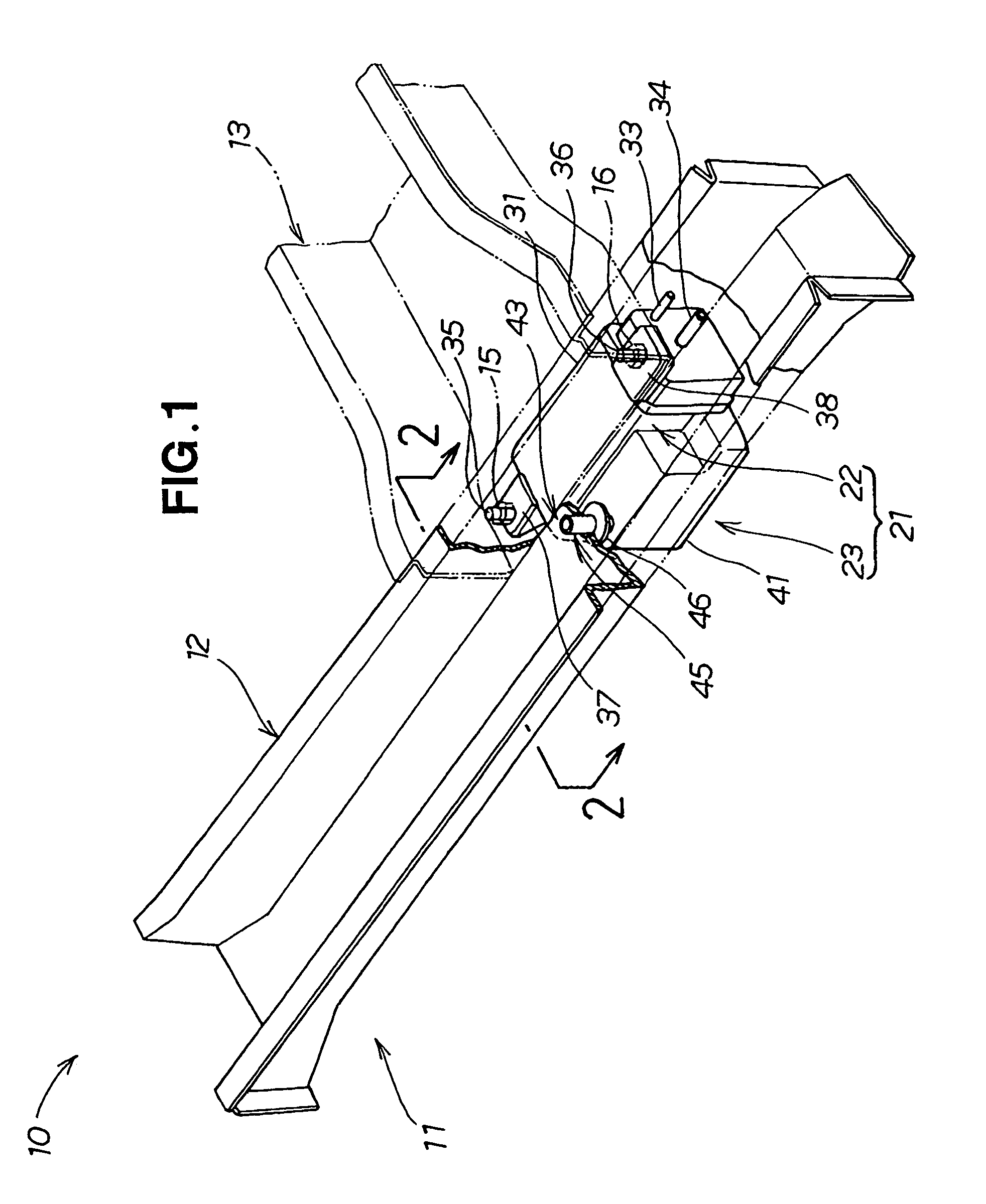
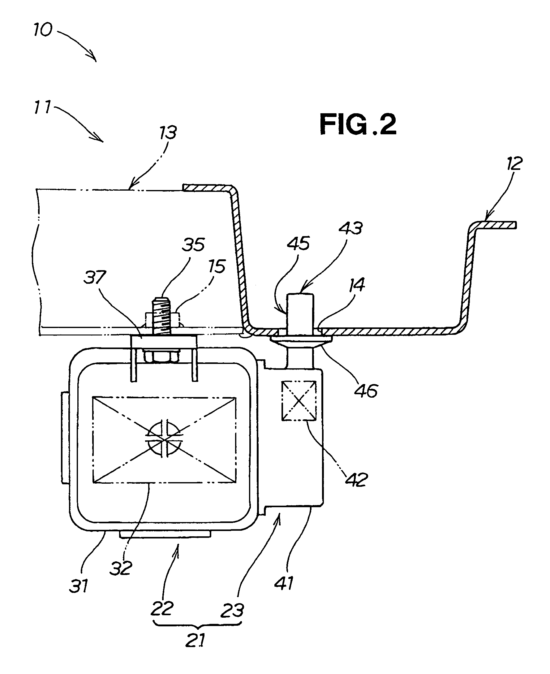
first embodiment
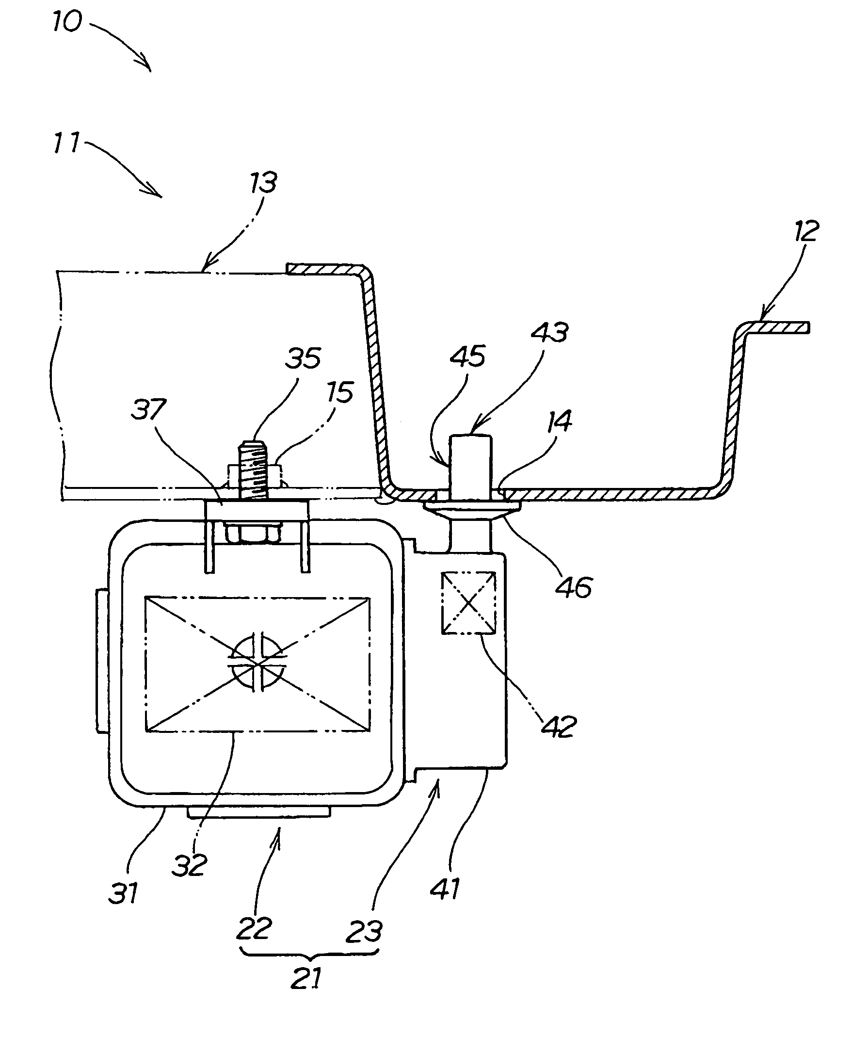
[0036]In the canister attachment structure 10 of the first embodiment, the air communication part 43 is disposed within the body forming member (floor frame) 12 by directly inserting the air communication part 43 of the canister filter 23 or the canister 21 into the body forming member 12, where the air communication part 43 is formed as an integral part of the filter housing. The drain tube extending from the air communication part 43 in the conventional canister filter 23 is accordingly obviated. As a result, it is possible to reduce the number of man-hours required for installation, and lower the cost. As seen best in FIG. 2, in the arrangement according to the present invention, the filter housing portion 41 of the canister 21 is substantially entirely disposed below the floor frame member 12, and the filter element 42 is disposed below, and proximate the insertion hole 14 formed in the body forming member (floor frame) 12, and the insertion part 45 extends substantially along a...
second embodiment
[0037]The canister attachment structure of the second embodiment is shown in FIGS. 3 and 4.
[0038]The canister attachment structure 60 of a second embodiment comprises a canister 71 attached to a bottom surface of a floor frame 62 and a cross-member 63, which constitute a vehicle body 61. The floor frame 62 and the cross-member 63 are body forming members constituting the vehicle body 61.
[0039]The floor frame 62 has an insertion hole 64 formed so that an insertion part 95 of an air communication part 93 passes therethrough. The insertion part 95 is locked by a surrounding part forming the insertion hole 64. Specifically, the insertion hole 64 functions as a locking hole for preventing the insertion part 95 from falling out of the floor frame.
[0040]The cross-member 63 has a canister attachment part 66 for attaching the canister 71 to the cross-member 63.
[0041]The canister 71 comprises the canister body 72 and a canister filter (dust filter) 73.
[0042]The canister body 72 has a canister...
PUM
 Abstract
Description
Claims
Application Information