Food extruder

a technology of extruder and rotating screw, which is applied in the direction of dough shaping, manufacturing tools, applications, etc., can solve the problems of not being able to choose between manual operation and prior art, and not being able to provide the above combination, etc., to facilitate insertion and secure the effect of the screw

Inactive Publication Date: 2010-10-12
SCHNEE CHRISTINE MARIE
View PDF9 Cites 7 Cited by
  • Summary
  • Abstract
  • Description
  • Claims
  • Application Information

AI Technical Summary

Benefits of technology

[0006]The present invention is a food extruder including a barrel provided at one end with an outlet from which the food substance can be extruded, a rotatable screw positioned within the barrel that is capable of being rotated and moved longitudinally within the barrel, a handle member at a top end of the rotatable screw for manual engagement, and a rod member protruding from an upper portion of the handle member for insertion into a drill chuck. The rod member, in a preferred embodiment, has a hexagonal cross section, which facilitates insertion and securement within a drill chuck, so that the drill may be used to turn the rotatable screw, rather than having to turn it manually. Additionally, a hand grip member may be attached to the barrel member at a generally right angle thereto, so that a user may grip the hand grip while using the drill to turn the rotatable screw, in order to prevent the entire extruder from rotating.

Problems solved by technology

However, manually turning the rotating screw quickly becomes tiresome, and none of the prior art allows a person to choose between manual operation and operation by using any type of hand-held drill.
Further, none of the prior art provides the above combination together with a hand grip extending from the barrel to prevent rotation of the entire apparatus while turning the rotating screw.

Method used


Image

  • Food extruder
  • Food extruder
  • Food extruder

Examples


Embodiment Construction

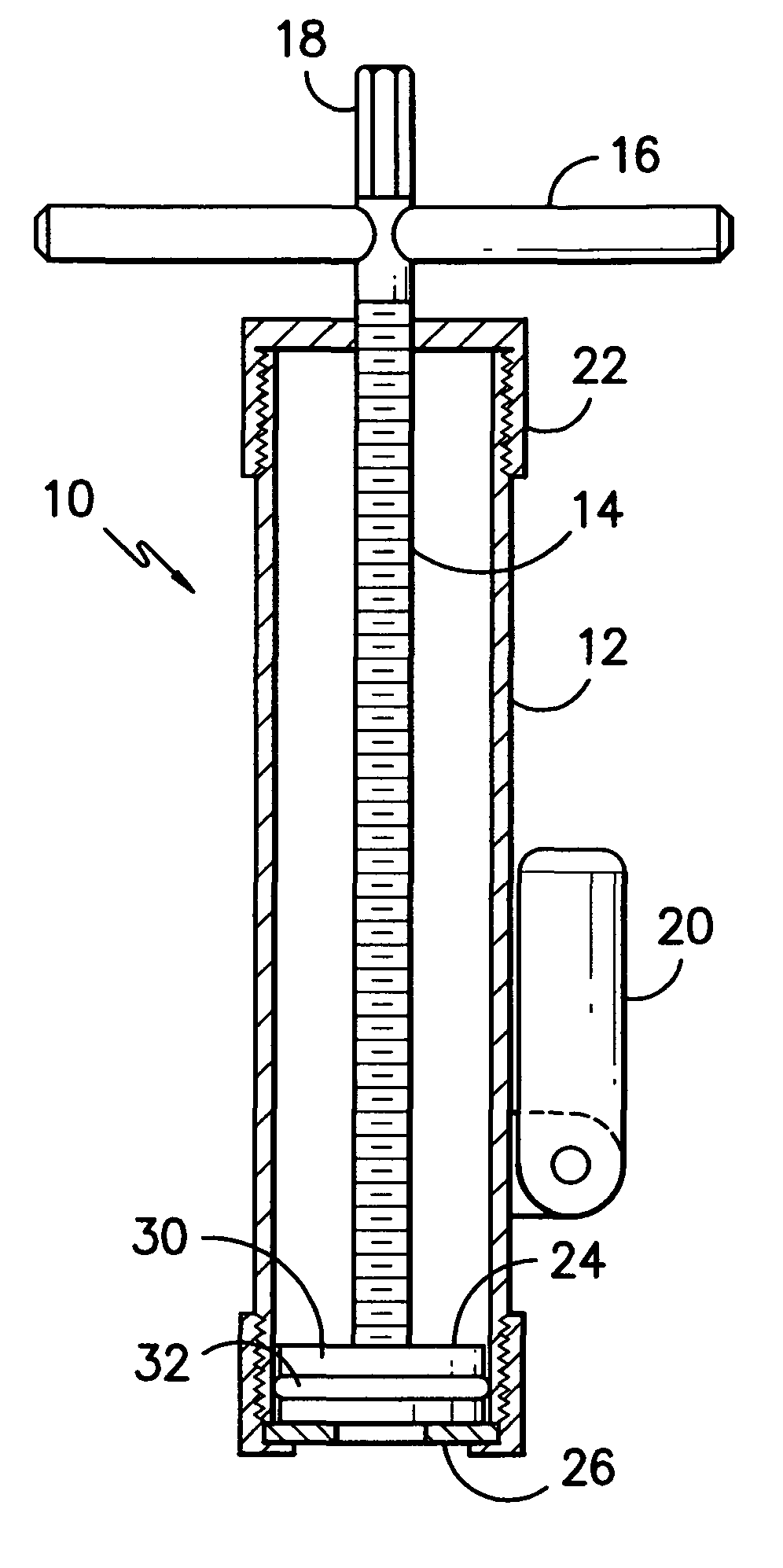
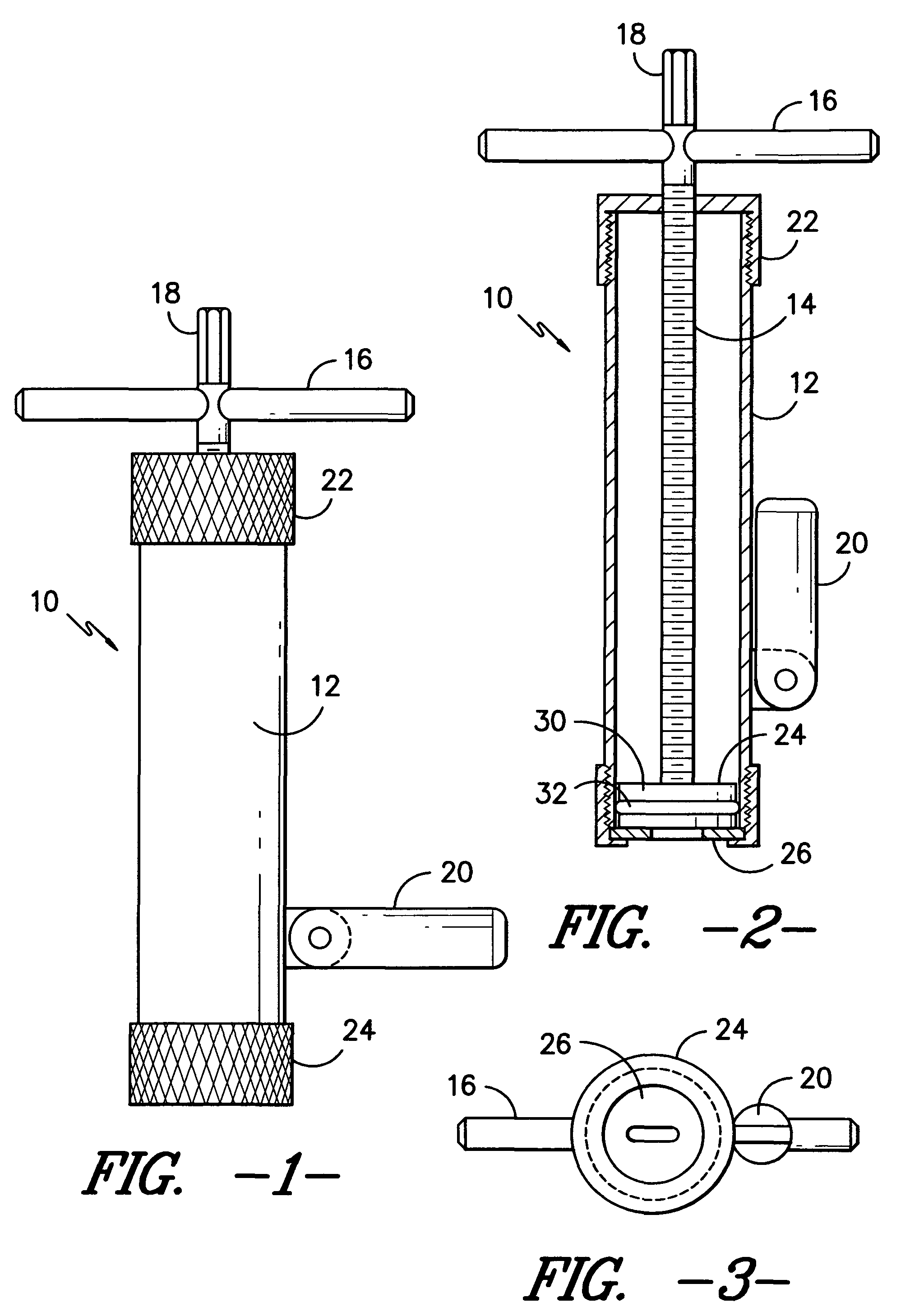
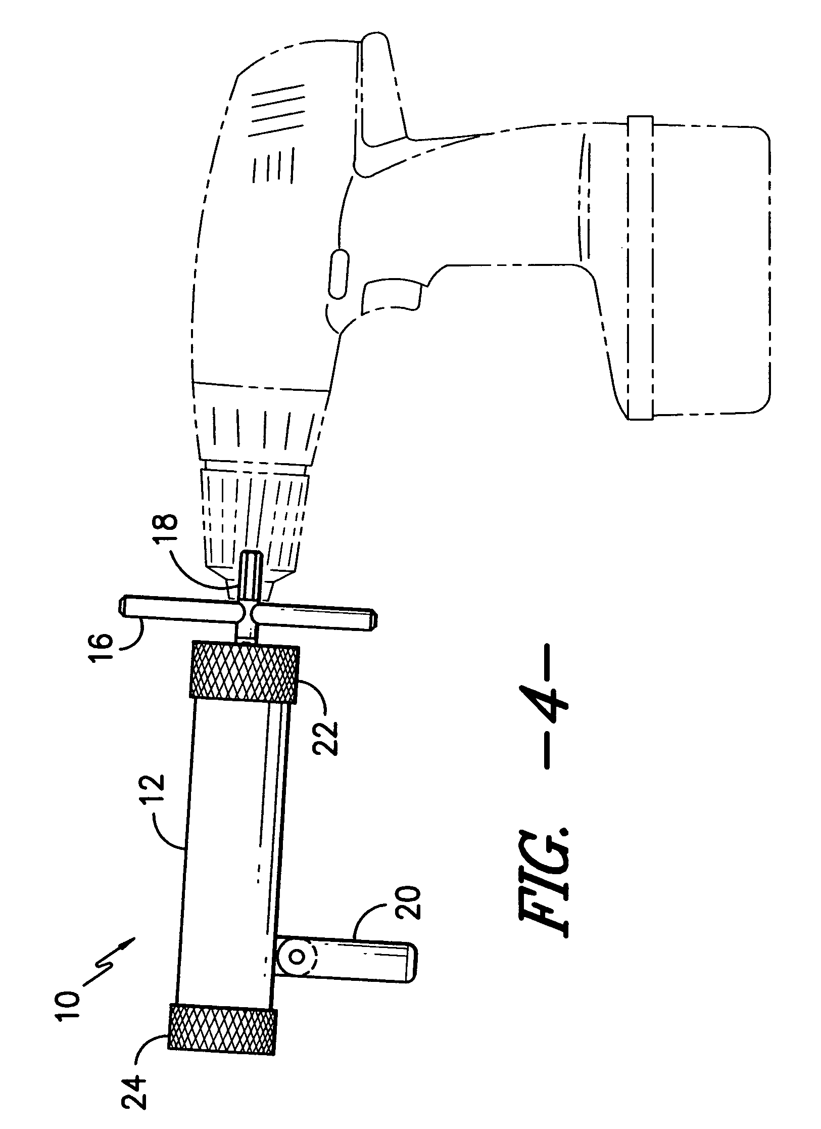
[0016]A first embodiment of the food extruder is shown in FIG. 1. The food extruder 10 includes a barrel 12 provided at a bottom end with an outlet from which the food substance can be extruded, a rotatable screw 14 positioned within the barrel 12 that is capable of being rotated and moved longitudinally within the barrel 12, a handle member 16 at a top end of the rotatable screw 14 to manually turn the rotatable screw 14, and a rod member 18 protruding from an upper portion of the handle member 16 for insertion into a drill chuck. The rod member 18, in a preferred embodiment, has a hexagonal cross section, which facilitates insertion and securement within a drill chuck, so that the drill may be used to turn the rotatable screw 14, rather than having to turn it manually. Additionally, a hand grip member 20 may be attached to the barrel 12 at a generally right angle thereto, so that a user may grip the hand grip 20 while using the drill to turn the rotatable screw 14, in order to pre...


PUM

PropertyMeasurementUnit
sizeaaaaaaaaaa
shapeaaaaaaaaaa
forceaaaaaaaaaa

Abstract

A food extruder including a barrel provided at one end with an outlet from which the food substance can be extruded, a rotatable screw positioned within the barrel that is capable of being rotated and moved longitudinally within the barrel, a handle member at a top end of the rotatable screw for manual engagement, and a rod member protruding from an upper portion of the handle member for insertion into a drill chuck. The rod member, in a preferred embodiment, has a hexagonal cross section, which facilitates insertion and securement within a drill chuck, so that the drill may be used to turn the rotatable screw, rather than having to turn it manually. Additionally, a hand grip member may be attached to the barrel member at a generally right angle thereto, so that a user may grip the hand grip while using the drill to turn the rotatable screw, in order to prevent the entire extruder from rotating.

Description

BACKGROUND OF THE INVENTION[0001]1. Field of the Invention[0002]The present invention relates generally to extruding devices used in conjunction with food substances. More specifically, the present invention is a food extruder including a barrel, where the food substance is placed, and a rotating screw with a head inside the barrel that drives the food substance through the barrel to an outlet. The rotating screw may be turned manually, or may be attached to and driven by a standard hand held drill.[0003]2. Description of the Prior Art[0004]Heretofore, efforts have been made to develop food extruders for various types of food substances. There are many types of extruders available today, particularly pasta extruders, and most of those devices are either mounted to a table, or are large enough to sit on a table or platform. Additionally, handheld food extruders are in existence. U.S. Pat. No. 5,933,188 is one such example. This food extruder includes a rotatable screw member within t...

Claims


Application Information

Patent Timeline
Patent Type & Authority Patents(United States)
IPC IPC(8): A23P1/12
CPCA21C15/005A23P1/12A47J9/002A23P30/20
Inventor SCHNEE, CHRISTINE MARIE
Owner SCHNEE CHRISTINE MARIE
Why Eureka
Try Eureka