Co-planar shielded write traces for disk drive head suspensions

Active Publication Date: 2010-10-12
HUTCHINSON TECH
View PDF28 Cites 24 Cited by
  • Summary
  • Abstract
  • Description
  • Claims
  • Application Information

AI Technical Summary

Benefits of technology

[0005]The present invention is an integrated lead head suspension flexure that provides enhanced signal transmission bandwidth without increases in impedance. One embodiment of the flexure includes a spring metal base layer, an insulating layer on the base layer and traces on the insulating layer. The traces comprise first an

Problems solved by technology

Unfortunately, optimizing features of the suspensions to meet these goals is increasingly difficult.
But constraints on the size of portions of the flexure traversed by the traces can limit the size of

Method used


Image

  • Co-planar shielded write traces for disk drive head suspensions
  • Co-planar shielded write traces for disk drive head suspensions
  • Co-planar shielded write traces for disk drive head suspensions

Examples


Example

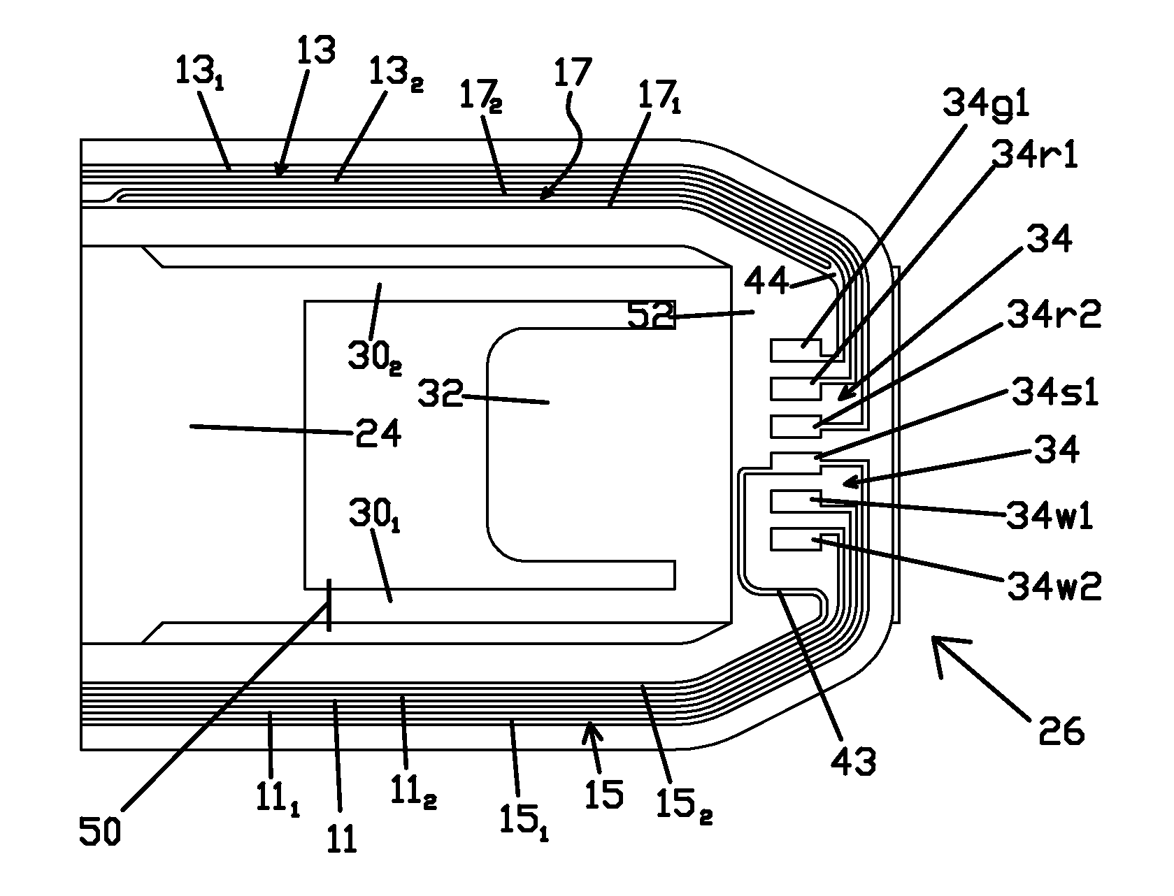
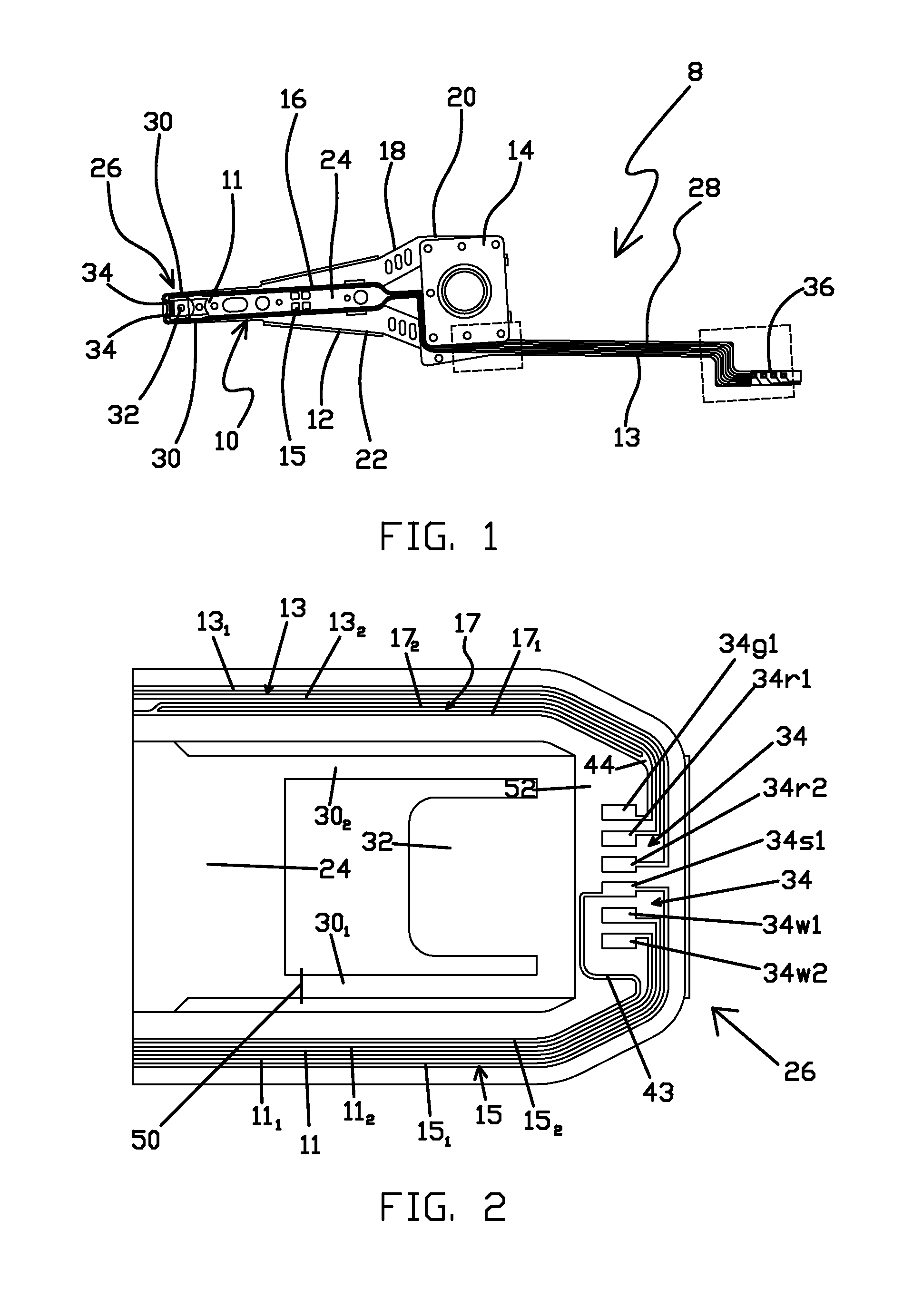
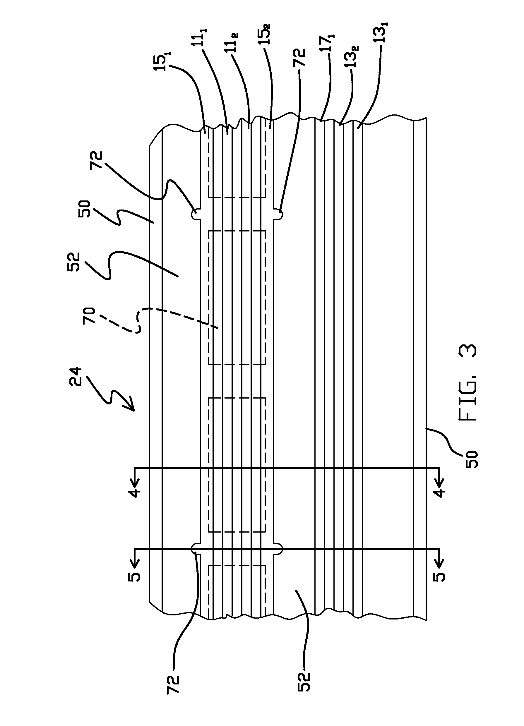
[0012]A disk drive head suspension 8 including a flexure 10 having co-planar shielded write traces 11 in accordance with one embodiment of the present invention is illustrated generally in FIG. 1. Suspension 8 is a three-piece assembly in the illustrated embodiment, and includes a load beam 12 and base plate 14 in addition to the flexure 10. Load beam 12, which is typically formed from stainless steel, includes a beam region 16, hinge or spring region 18 and mounting region 20. Rails 22 are formed on the side edges of the beam region 16. Base plate 14 is welded to the mounting region 20 at the proximal end of the load beam 12.

[0013]Flexure 10 is an integrated lead or wireless flexure and includes a mounting or base region 24 that is welded or otherwise attached to the beam region 16 of load beam 12, a gimbal region 26 at its distal end, and a tail 28 extending from the proximal end of the base region. The gimbal region 26 includes a pair of laterally-spaced spring arms 301 and 302 e...


PUM


Abstract

An integrated lead head suspension flexure including a spring metal base layer, an insulating layer on the base layer and traces on the insulating layer. The traces include first and second adjacent and co-planar write traces and first and second shield traces. The shielding traces are on opposite sides of the write traces, electrically interconnected and generally co-planar with the write traces. Portions of the stainless steel layer below the traces include windows. The shield traces can be connected to ground and/or to the spring metal base layer.

Description

FIELD OF THE INVENTION[0001]The present invention relates generally to disk drive head suspensions. In particular, the invention is an integrated lead flexure for a suspension.BACKGROUND OF THE INVENTION[0002]Disk drive head suspensions with wireless or integrated lead flexures are generally known and disclosed, for example, in the following U.S. Patents, all of which are incorporated herein by reference.[0003]Inventor NameU.S. Pat. No.Erpelding5,631,786Balakrishnan5,737,152Balakrishnan5,995,328Balakrishnan et al.6,038,102Balakrishnan et al6,275,358Shiraishi et al.6,839,204Kulangara et al.6,975,488[0004]The continuing development of read / write head and related disk drive technology requires head suspensions having improved mechanical and electrical specifications. For example, there is a need for suspensions having increased signal current carrying capabilities, higher data rates and reduced size. Unfortunately, optimizing features of the suspensions to meet these goals is increasin...

Claims


Application Information

Patent Timeline
IPC IPC(8): G11B5/48
CPCG11B5/486
Inventor HENTGES, REED T.
Owner HUTCHINSON TECH
Why Eureka
Try Eureka