
Mobile communication system, user equipment in mobile communication system, control program thereof, and transmission power control method in mobile communication system

a mobile communication system and control program technology, applied in power management, antennas, electrically long antennas, etc., can solve the problems of inability to determine crc, inability to measure bler, and inability to perform the above described outer loop control for matching the received bler with the target bler

Inactive Publication Date: 2010-10-12
NTT DOCOMO INC
View PDF7 Cites 2 Cited by
  • Summary
  • Abstract
  • Description
  • Claims
  • Application Information

AI Technical Summary

Benefits of technology

[0027]Therefore, even if the Blind transport format detection is used in the stand-alone communication state, it is possible to perform the transmission power control in accordance with a reception status of the user equipment, enabling the adequate transmission power control depending on change in the communication status.
[0034]Therefore, it is possible to use a parameter which is normally measured, to easily determine the reception quality of the common channel at low cost.
[0036]Therefore, it is possible to use a parameter which is normally calculated, to easily determine the reception quality of the common channel at low cost.
[0038]Therefore, it is possible to use a parameter which is normally measured, to easily determine the reception quality of the common channel at low cost.
[0042]Therefore, it is possible to perform the transmission power control in which the change in the communication status is more adequately reflected.
[0043]According to the present invention, even if the Blind transport format detection is used in the stand-alone communication state, it is possible to perform the transmission power control in accordance with the reception status of the user equipment, enabling the adequate transmission power control depending on the change in the communication status.

Problems solved by technology

Therefore, if the DTCH has not been set, the result of the CRC cannot be determined.
Consequently, also the BLER cannot be measured.
Thus, a situation occurs in which the above described outer loop control for matching the received BLER with the target BLER cannot be performed.
However, if the fixed value which has been previously defined as the target SIR in the outer loop control is used, since the target SIR is not changed, a power more than or equal to a certain level is not requested even though a reception quality has deteriorated, and thereby a situation occurs in which data transmission and reception are failed.
Conversely, an excessive transmission power is requested even though the reception quality has been improved, and thereby a situation occurs in which power consumption is increased or interference to another communication is caused.
Moreover, if the target SIR is determined based on the received data error rate of the pilot signal in the dedicated physical control channel, since the pilot signal in the dedicated physical control channel (DPCCH) is discretely transmitted and an information amount is limited, the target SIR to be set may not be an appropriate value.
However, the signal is transmitted even though there is no control information, which causes unnecessary power consumption, and also, although a CRC check has been completed at one time, the number of CRC checks increases twice in the Blind transport format detection under a condition of the StandAlone-DCCH.
In this way, it has been difficult to perform adequate transmission power control depending on a communication status if the Blind transport format detection is used in the stand-alone communication state.

Method used


Image

  • Mobile communication system, user equipment in mobile communication system, control program thereof, and transmission power control method in mobile communication system
  • Mobile communication system, user equipment in mobile communication system, control program thereof, and transmission power control method in mobile communication system
  • Mobile communication system, user equipment in mobile communication system, control program thereof, and transmission power control method in mobile communication system

Examples


Embodiment Construction

[0047]An embodiment of a W-CDMA wireless system applied with the present invention will be described below with reference to the drawings.

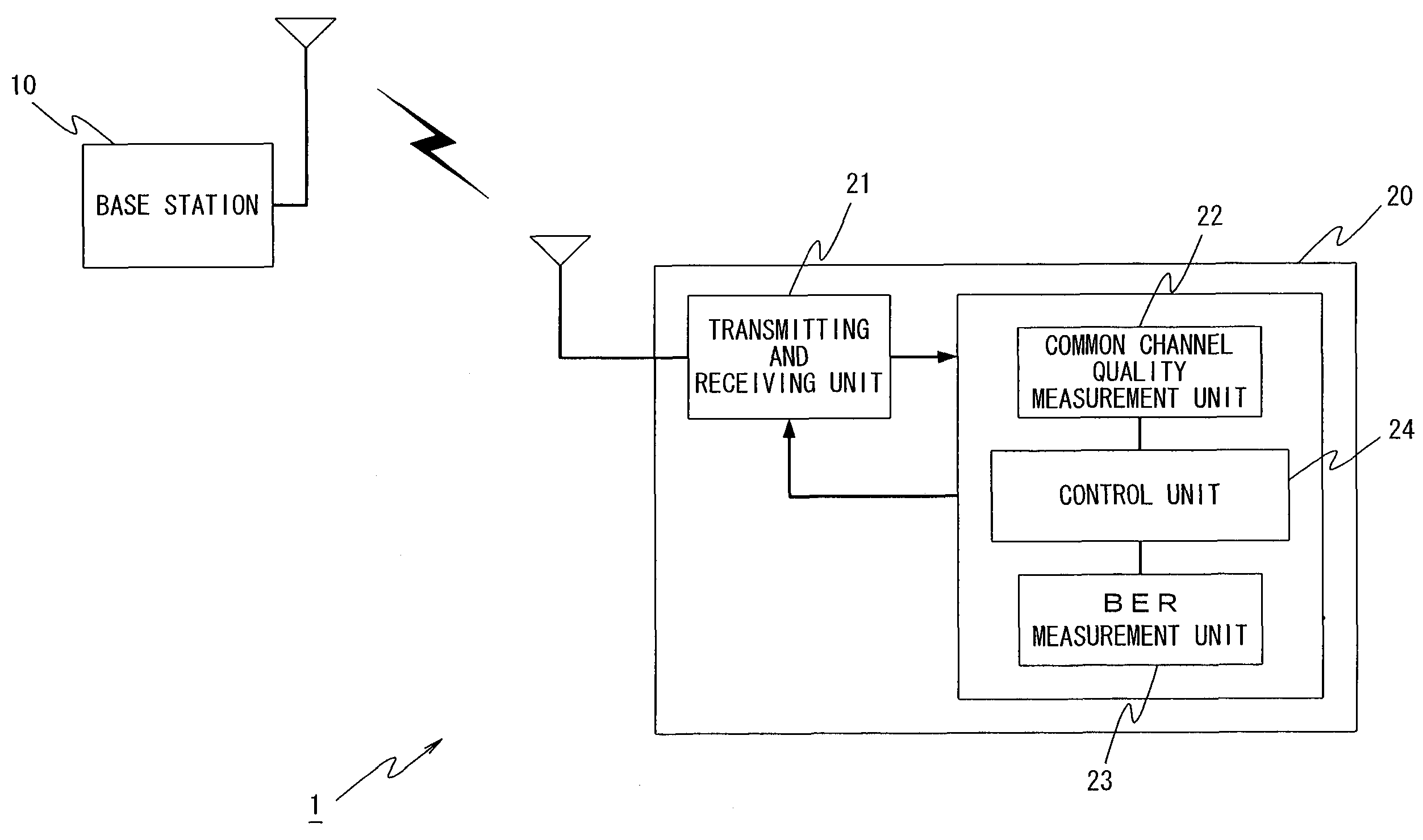
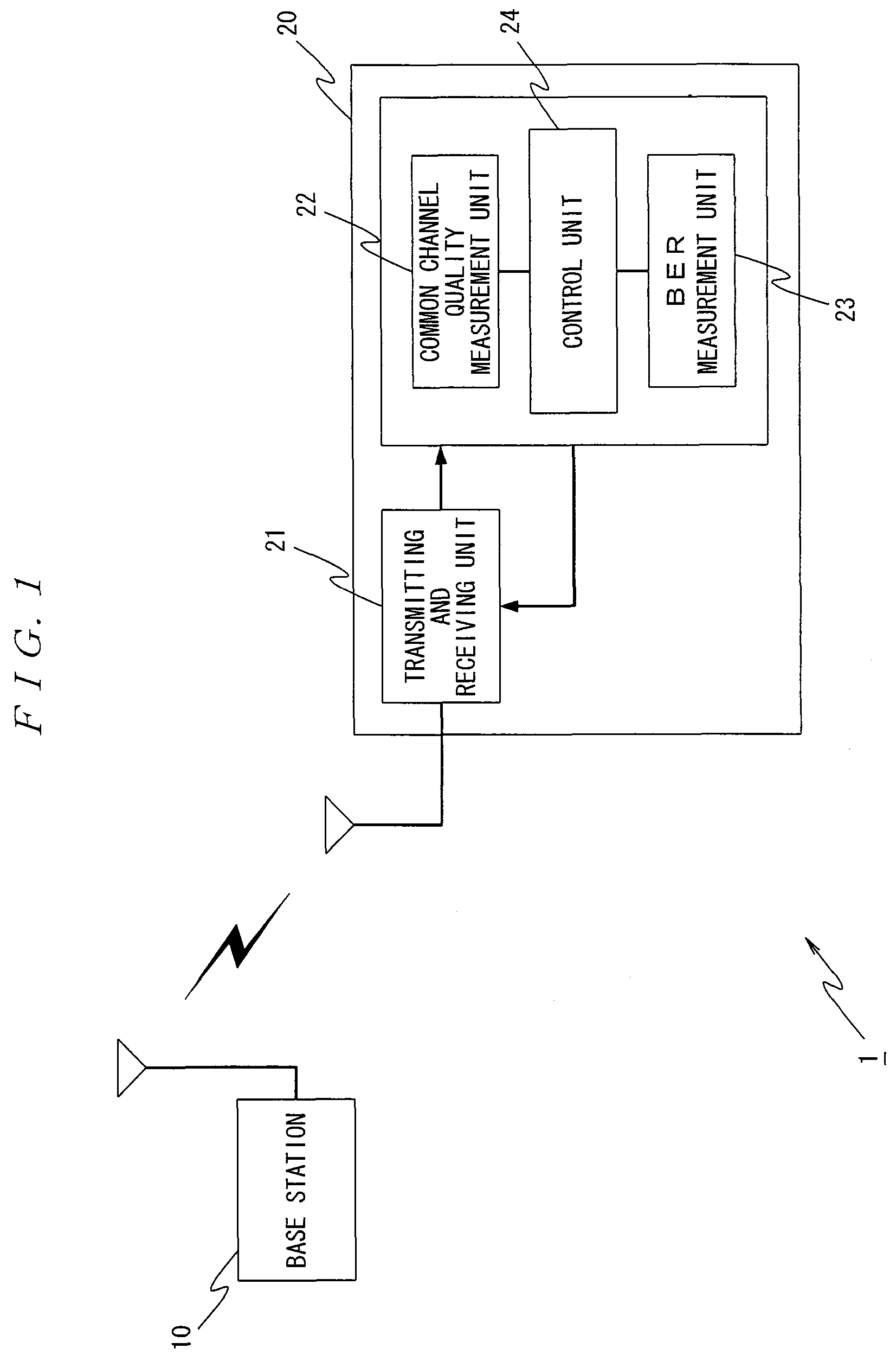
[0048]FIG. 1 is a schematic diagram showing a base station and a user equipment in a W-CDMA wireless system 1 according to the present invention.

[0049]In FIG. 1, the W-CDMA wireless system 1 includes a base station 10 and a user equipment 20.

[0050]The base station 10 is provided with a base station function in a mobile communication system using W-CDMA.

[0051]Specifically, the base station 10 establishes communication based on the W-CDMA with the user equipment 20 in a communicable area of the base station 10, and communicates with the user equipment 20 via physical channels including a common pilot channel (CPICH), a common control physical channel (CCPCH) and a dedicated physical channel (DPCH).

[0052]Among these channels, the common pilot channel is a channel for continuously transmitting a scrambling code (PN code) of the base station 10, and th...


PUM


Abstract

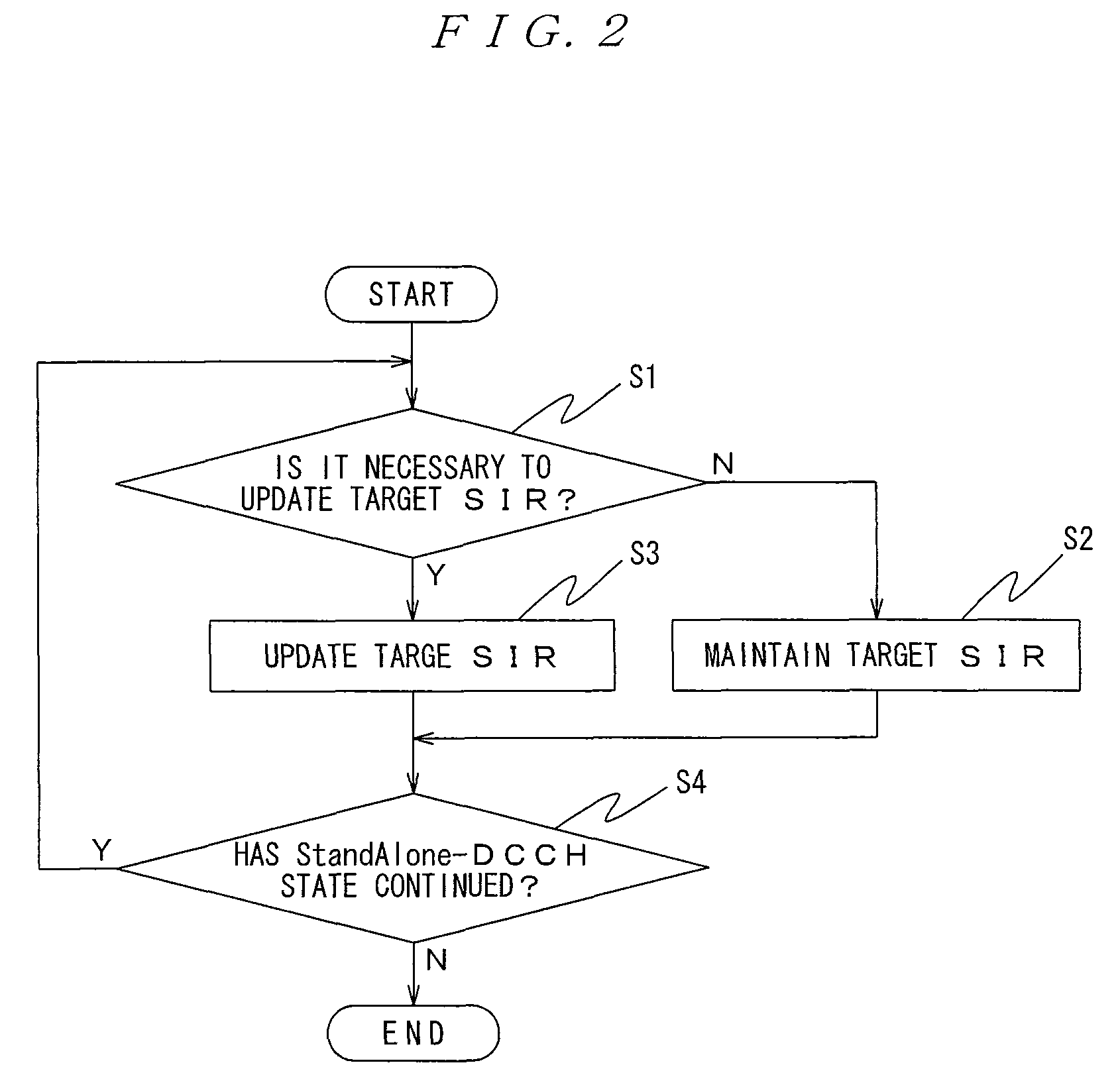
In a W-CDMA wireless system, when communication is performed by using a StandAlone-DCCH, adequate transmission power control is performed depending on change in a communication status. In a W-CDMA wireless system 1, a reception quality of a common channel is measured, and if a StandAlone-DCCH state has occurred, transmission power control corresponding to the common channel is performed in which a target SIR is determined depending on the reception quality of the common channel. Therefore, even in the StandAlone-DCCH state in which Blind transport format detection is used, it is possible to set the target SIR in accordance with a reception status of a user equipment 20, enabling the adequate transmission power control depending on the change in the communication status.

Description

BACKGROUND OF THE INVENTION[0001]1. Field of the Invention[0002]The present invention relates to a mobile communication system for providing communication services to user equipments, the user equipment in the mobile communication system, a control program thereof, and a transmission power control method in the mobile communication system.[0003]2. Description of the Related Art[0004]In recent years, a mobile communication system using W-CDMA (Wideband-Code Division Multiple Access) has been used as a multiple access method.[0005]In the mobile communication system using the W-CDMA (hereinafter appropriately referred to as “W-CDMA wireless system”), transmission power control is performed for maintaining a communication quality to a predetermined level.[0006]Moreover, in various environments, in order to more stably maintain the communication quality, closed-loop transmission power control having a double-loop structure consisting of inner loop control and outer loop control may be pe...

Claims


Application Information

Patent Timeline
Patent Type & Authority Patents(United States)
IPC IPC(8): H04B7/00H04W52/28
CPCH04W52/12H04W52/241H04W52/287
Inventor OKAMOTO, ETSUHIROOKUMURA, YUKIHIKOKITAYAMA, TETSURO
Owner NTT DOCOMO INC
Learn More