In-vivo imaging device, optical system and method

a technology of in-vivo imaging and optical system, which is applied in the field of in-vivo imaging devices, can solve the problems of difficult to push devices through the intestines or other body lumens without potentially causing a lesion or tear of the body lumen wall,

Inactive Publication Date: 2010-10-12
GIVEN IMAGING LTD
View PDF144 Cites 17 Cited by
  • Summary
  • Abstract
  • Description
  • Claims
  • Application Information

AI Technical Summary

Problems solved by technology

It may be difficult to push devices through the intestines or other body lumens without potentially causing a lesion or tear of the body lumen wall.

Method used


Image

  • In-vivo imaging device, optical system and method
  • In-vivo imaging device, optical system and method
  • In-vivo imaging device, optical system and method

Examples


Embodiment Construction

[0028]In the following description, various aspects of the present invention will be described. For purposes of explanation, specific configurations and details are set forth in order to provide a thorough understanding of the present invention. However, it will also be apparent to one skilled in the art that the present invention may be practiced without the specific details presented herein. Furthermore, well known features may be omitted or simplified in order not to obscure the present invention.

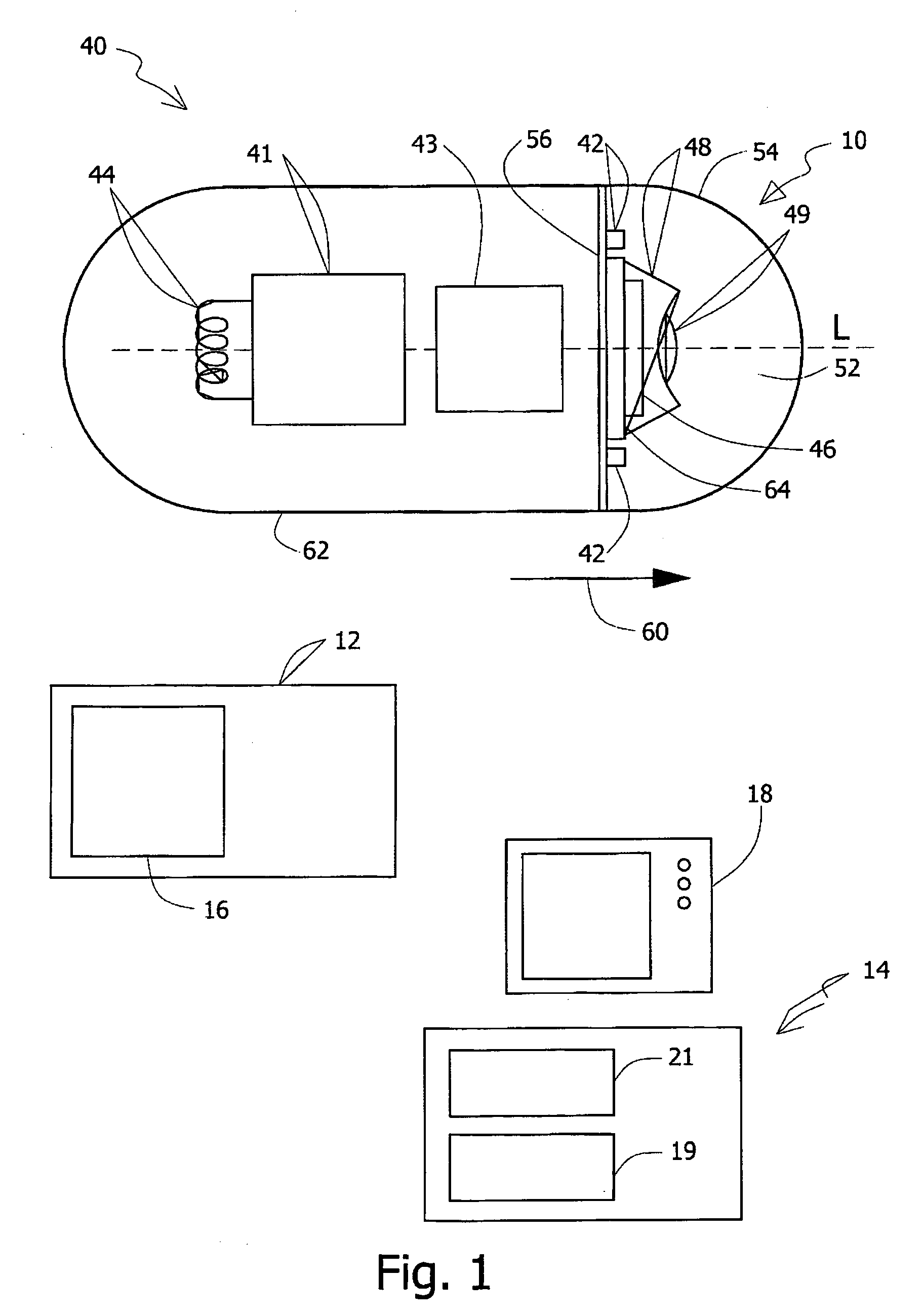
[0029]It will be appreciated that the terms “receiving unit” and “imaging unit” relate to any unit suitable for receiving, processing or further transmitting illumination rays remitted from a target or data derived from these rays. For example, an imager or camera, such as a Charge Coupled Device (CCD) camera or imager or a Complementary Metal Oxide Semiconductor (CMOS) imager or camera may be used; other suitable receiving or imaging units may be used.

[0030]Embodiments of the present in...


PUM


Abstract

An in-vivo device may include an optical system, and a method for viewing in-vivo sites. A dome or cover may cover an end of the device, protecting optical elements such as illumination devices or imagers, which may be behind the dome. The dome may be forward projecting and may have a convex shape. The field of view of the imager may be for example forward looking. Illumination element(s) and a receiving unit or imager may be disposed behind a single optical window, which for example may enable obtaining of images free of backscatter and stray light. The convex shape of the dome may be defined such that it may have a shape having an isolated area. At least one illumination element and at least one receiving unit may be geometrically positioned (for example in the isolated area) such that rays from the illumination elements, some of which are internally reflected from the internal and / or external surface of the optical window, will not be incident on the receiving unit.

Description

CROSS REFERENCE TO RELATED APPLICATIONS[0001]This application is a continuation-in-part of U.S. application Ser. No. 10 / 879,483 filed on 30 Jun. 2004, entitled “In-Vivo Imaging Device, Optical System and Method” which in turn is a continuation-in-part of U.S. application Ser. No. 10 / 009,837 filed on 22 Aug. 2002, entitled “An Optical System”, now U.S. Pat. No. 6,836,377 which is a national phase application of International Application PCT / IL00 / 00349 filed 15 Jun. 2000, and a continuation-in-part of U.S. application Ser. No. 10 / 478,252 filed on 20 Nov. 2003, entitled “A Method for In Vivo Imaging of an Unmodified Gastrointestinal Tract”, which is a national phase application of International Application PCT / IL02 / 00391 filed 20 May 2002, all of which are incorporated in their entirety by reference herein. International Application PCT / IL00 / 00349 filed 15 Jun. 2000 claims benefit from Israeli Patent Application No. IL 130486 filed 15 Jun. 1999. International Application PCT / IL02 / 00391...

Claims


Application Information

Patent Timeline
Patent Type & Authority Patents(United States)
IPC IPC(8): A61B6/00
CPCA61B1/00096A61B1/041A61B1/05A61B1/0676A61B1/0684
Inventor GLUKHOVSKY, ARKADY
Owner GIVEN IMAGING LTD
Why Eureka
Try Eureka