Solar panel mounting systems

Active Publication Date: 2010-10-19
SOLARSTRAP TECH LLC
View PDF11 Cites 102 Cited by
  • Summary
  • Abstract
  • Description
  • Claims
  • Application Information

AI Technical Summary

Benefits of technology

[0011]The present invention is a solar panel mounting system that minimizes the number of attachm

Problems solved by technology

Existing mounting structures are often limited as to the type of surface to which they can be attached, their abi

Method used


Image

  • Solar panel mounting systems
  • Solar panel mounting systems
  • Solar panel mounting systems

Examples


Embodiment Construction

[0033]While the present invention is described herein with reference to illustrative embodiments for particular applications, it should be understood that the invention is not limited thereto. Those having ordinary skill in the art and access to the teachings provided herein will recognize additional modifications, applications, and embodiments within the scope thereof and additional fields in which the present invention would be of significant utility.

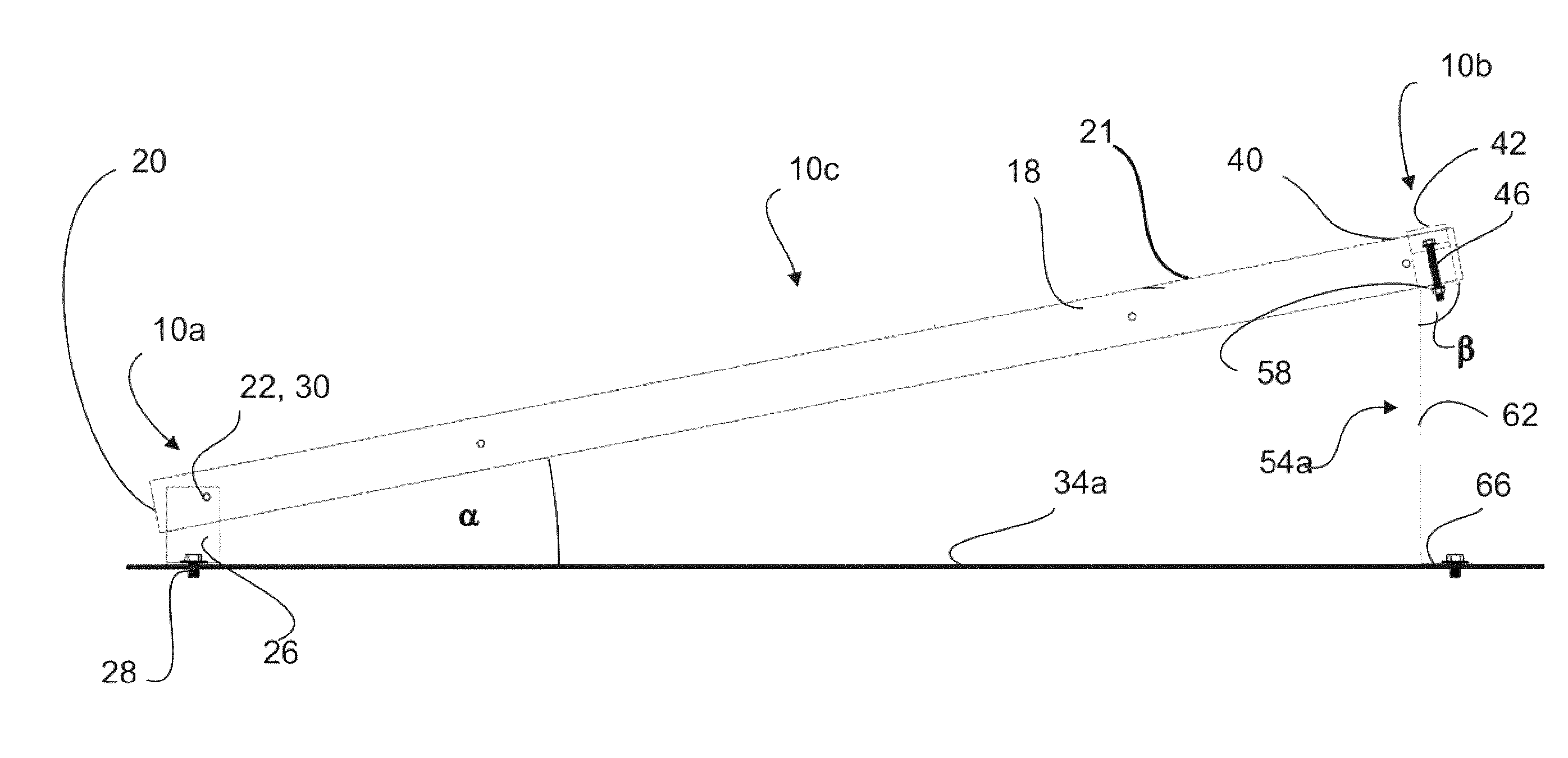
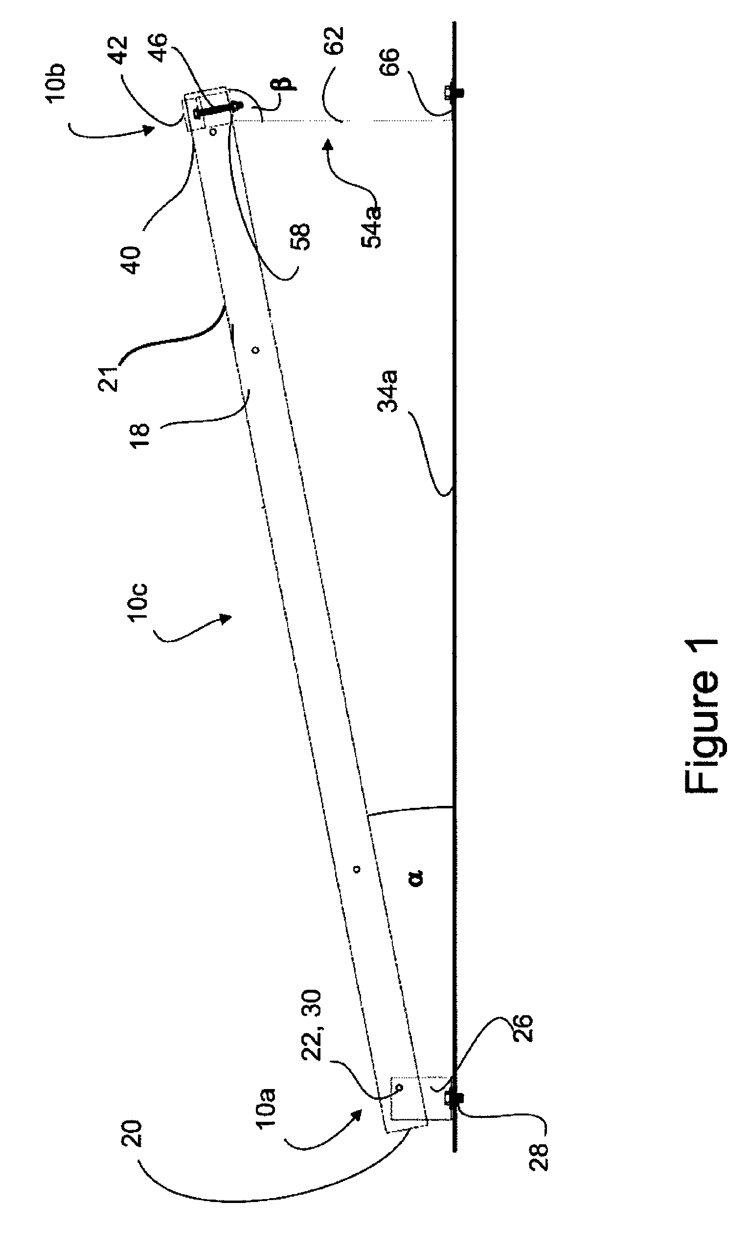
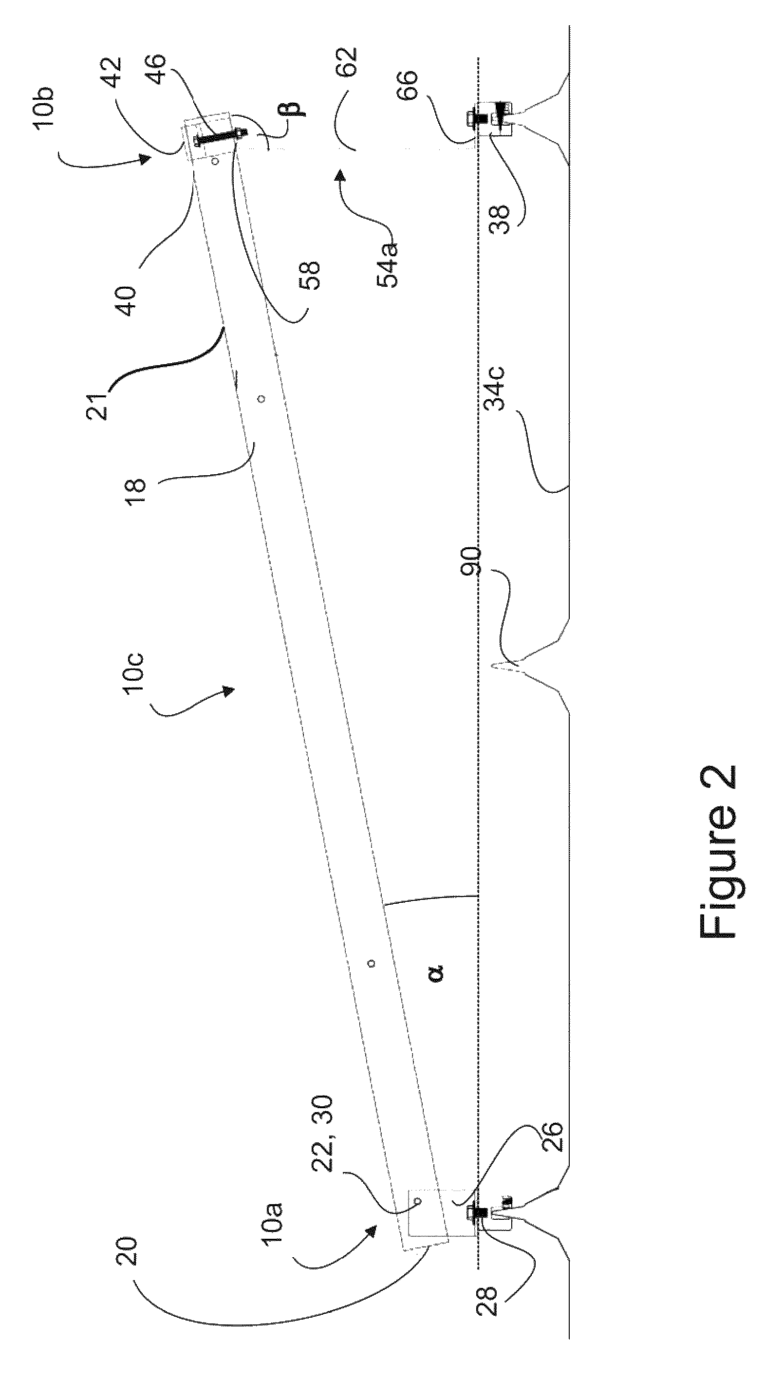
[0034]The first embodiment 10a of this invention, also known as the pivot end, is illustrated in FIGS. 1, 2, 3, 6, 7, 9 and 11. This embodiment 10a is applied to a solar collector panel 14 with frame 18 that has at least one through hole 22 near one end 20, which extends perpendicular to the frame 18. One solar panel 14 with frame 18 with which this invention may be used is the Schott ASE 310-W Solar Module. The embodiment 10a comprises a bracket 26. This bracket 26 can be any one of a variety of shapes, including L 26a, T 26b, or U 2...


PUM


Abstract

In a first embodiment a framed solar panel is retained by a rod inserted through a hole in the panel frame. The rod is attached to the top of a bracket, which is mounted at its bottom to a substantially flat surface. In a second embodiment, a framed solar collector panel is retained by a clip which is designed to fit over the top edge of the frame. The clip is then attached to the top of a second bracket. In a fourth embodiment a tether is fastened between the through hole and the flat surface. These embodiments may be used at either or both ends of the frame. Each embodiment may include a safety tether that is connected between the frame and the bracket.

Description

BACKGROUND OF THE INVENTION[0001]1. Field of the Invention[0002]The present invention relates to the field of solar energy collection. More specifically, this invention is directed toward a method of attaching solar collecting panels to a wide array of mounting surfaces.[0003]2. Description of Prior Art[0004]Solar panels are typically mounted on a mounting structure, which is supported on a mounting surface, such as a rooftop. Existing mounting structures are often limited as to the type of surface to which they can be attached, their ability to affix adjoining panels with a single system, and / or the positioning of the panels on the mounting surface.[0005]There have been a number of developments in this area. U.S. Pat. No. 6,360,491 (Ullman) discloses an L-shaped end clamp used to secure a solar panel. The end clamp has a hole for alignment with a threaded hole on a horizontal rod insert. The end clamp further has a notched surface for frictionally engaging the solar panel and secur...

Claims


Application Information

Patent Timeline
IPC IPC(8): E04D13/18E04H14/00
CPCF24J2/5211F24J2/5233F24J2/5249F24J2/5252F24J2/5258Y02E10/47F24S25/615F24S25/13F24S25/20F24S25/63F24S25/636
Inventor PORT, JONATHAN
Owner SOLARSTRAP TECH LLC
Why Eureka
Try Eureka