Quick coupling

a technology of coupling and coupling plate, applied in the direction of couplings, water supply installations, mechanical devices, etc., can solve the problems of not being satisfied with the results, and achieve the effects of improving the hydrodynamic conditions, reducing load losses, and increasing the oil flow ra

Active Publication Date: 2010-10-19
FASTER SPA
View PDF15 Cites 9 Cited by
  • Summary
  • Abstract
  • Description
  • Claims
  • Application Information

AI Technical Summary

Benefits of technology

[0005]Accordingly, the aim of the present invention is to overcome the above mentioned drawbacks of the prior art and provide a quick coupling having a constructional length less than that of prior devices, while improving their hydrodynamic conditions, and allowing to greatly increase the oil flow rate and reduce the load losses.

Problems solved by technology

Several attempts have been made in the prior art both to reduce the constructional length of the quick couplings and to obtain improvements, from a hydrodynamic standpoint in the related devices; however, the achieved results have not been found to be very satisfactory.

Method used


Image

  • Quick coupling
  • Quick coupling
  • Quick coupling

Examples


Embodiment Construction

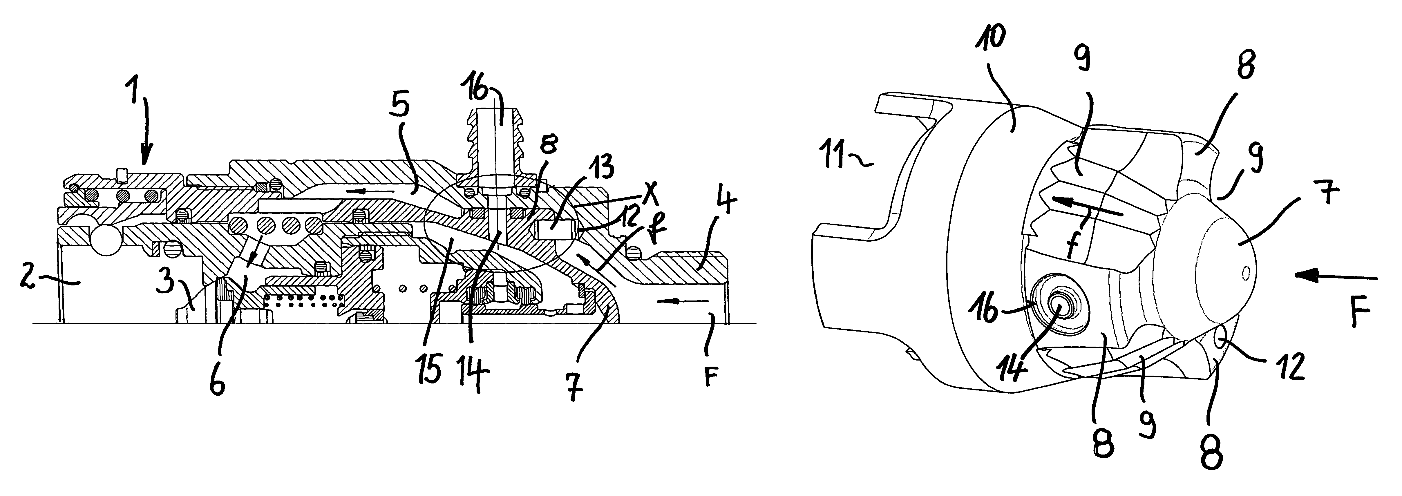
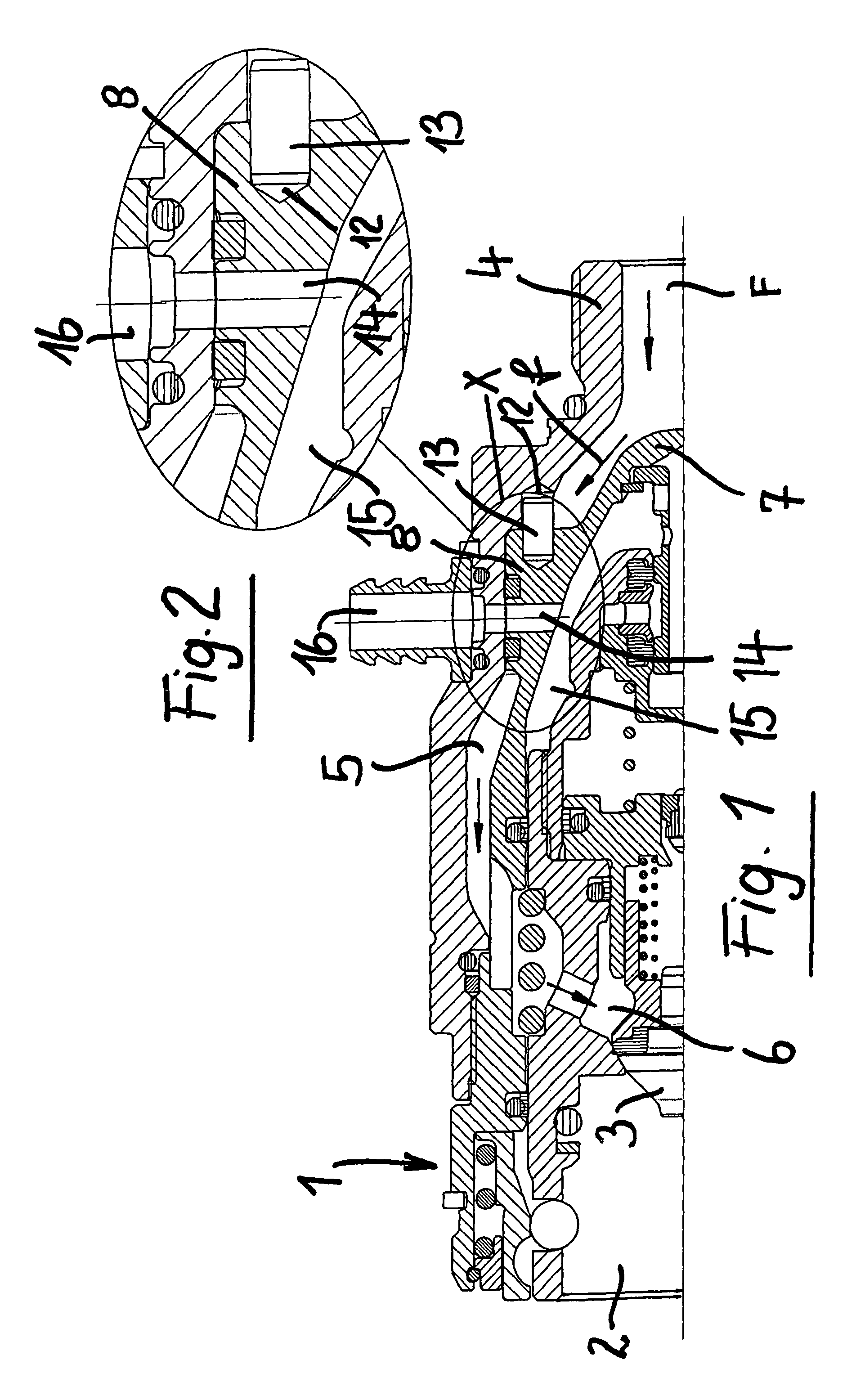
[0011]As shown in FIG. 1, the female type of quick coupling 1, comprises a port 2 for engaging therein a male coupling, not shown.

[0012]The port 2 is shut-off or closed by an axially movable valve body 3, of a per se known type.

[0013]At a position opposite to the port 2, the quick coupling 1 comprises a fitting 4 to which a duct for supplying a pressurized fluid F, conveyed in the direction shown by the arrows (f), can be connected.

[0014]The fluid F is conveyed along a conveying channel 5 with a smooth arch arrangement, formed inside the valve body 1, and ending at an annular chamber 6 shut-off or closed by the valve body 3 toward the male element coupling port 2.

[0015]As shown, the channel 4 gradually extends along an arch extension.

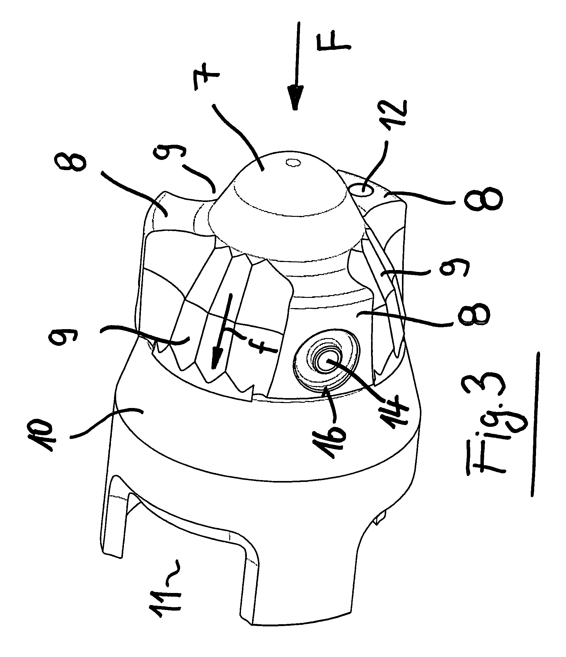
[0016]Immediately downstream of the fitting 4, the flow F will encounter a guide and conveying body 7, which is shown by a perspective view in FIG. 3.

[0017]From FIG. 3 it should be apparent that the fluid F guide and conveying body 7 has a substantially...


PUM


Abstract

A quick coupling, for example of a female type, to be connected with a counterpart, of a male type, comprises, inside a valve body, downstream of an inlet fitting for receiving a pressurized fluid flow (F), a guide and conveying body (7) having a parabolic cross section, and a plurality of radially outwardly extending ribs, delimiting, circumferentially of the guide and conveying body, a plurality of flow channels communicating with an annular chamber (6) closed by a valve body (3).

Description

BACKGROUND OF THE INVENTION[0001]The present invention relates to a quick coupling, for example of a female type, which can be coupled to a male type of counterpart.[0002]As is known, quick coupling users frequently require to greatly increase the oil flow rate while reducing load losses in devices to which the quick couplings are fitted.[0003]Moreover, it has been found as greatly advantageous to reduce the length of the individual components of the quick coupling.[0004]Several attempts have been made in the prior art both to reduce the constructional length of the quick couplings and to obtain improvements, from a hydrodynamic standpoint in the related devices; however, the achieved results have not been found to be very satisfactory.SUMMARY OF THE INVENTION[0005]Accordingly, the aim of the present invention is to overcome the above mentioned drawbacks of the prior art and provide a quick coupling having a constructional length less than that of prior devices, while improving thei...

Claims


Application Information

Patent Timeline
Patent Type & Authority Patents(United States)
IPC IPC(8): F16K51/00
CPCF16L37/42Y10T137/87957
Inventor AROSIO, MASSIMO
Owner FASTER SPA
Why Eureka
Try Eureka