Sealing structure for cabin

a sealing structure and cabin technology, applied in the field of cabins, can solve the problems of weak restoring force due to elastic deformation of the seal material, water can easily leak into the cab, so as to prevent water from stagnating, improve sealing performance, and improve sealing performance

Active Publication Date: 2010-10-19
KUBOTA LTD
View PDF33 Cites 28 Cited by
  • Summary
  • Abstract
  • Description
  • Claims
  • Application Information

AI Technical Summary

Benefits of technology

[0005]The object of this invention is to realize a seal structure for a cab that produces improved sealing performance between an outer roof and a cab frame.
[0011]According to this characteristic, drain grooves are formed laterally of the body portion of the seal material for draining water entering between the seal material and the cab frame. The water entering between the seal material and the cab frame can be drained smoothly through the drain grooves. Thus, water is prevented from stagnating between the seal material and the cab frame.
[0012]The body portion and seal lips of the seal material have sealing effects in two locations between the outer roof and cab frame. This improves sealing performance between the outer roof and cab frame.
[0013]That is, according to this invention, since water is prevented from stagnating between the seal material and cab frame, water can hardly enter the cab from between the seal material and cab frame, thereby improving sealing performance between the outer roof and cab frame.

Problems solved by technology

When, for example, the seal member becomes depleted or the tightening force weakens, there arises a problem that water can easily leak into the cab.
However, the restoring force due to the elastic deformation of the seal material is weak.
When, for example, the seal material becomes depleted, there arises a problem that water can easily leak into the cab.

Method used


Image

  • Sealing structure for cabin
  • Sealing structure for cabin
  • Sealing structure for cabin

Examples


first modified embodiment

of the Invention

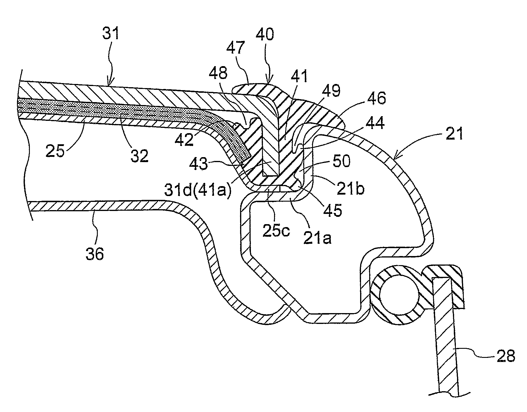
[0064]In the above embodiment, the outer roof 31 with the seal materials 40 attached thereto is fixed to the cab frame 21 with bolts 35 from above. A different construction may be employed used for fastening and fixing the outer roof 31 with the seal materials 40 attached thereto to the cab frame 21 from above.

[0065]In the above embodiment, the seal materials 40 are used to seal gaps between outer roof 31 and door frame 21 at the opposite sides of the outer roof 31. It is possible to employ a different construction where the seal materials 40 seal gaps between the outer roof 31 and other frames constituting the cab frame 21. For example, the seal materials 40 may be attached over the entire circumference of the outer roof 31.

second modified embodiment

of the Invention

[0066]In the above embodiment, the seal lips 42-45, drain grooves 48-50 and the first and second tongues 46 and 47 have the described shapes. The seal lips 42-45, drain grooves 48-50 and the first and second tongues 46 and 47 of other shapes may be employed as long as similar functions are fulfilled.

third modified embodiment

of the Invention

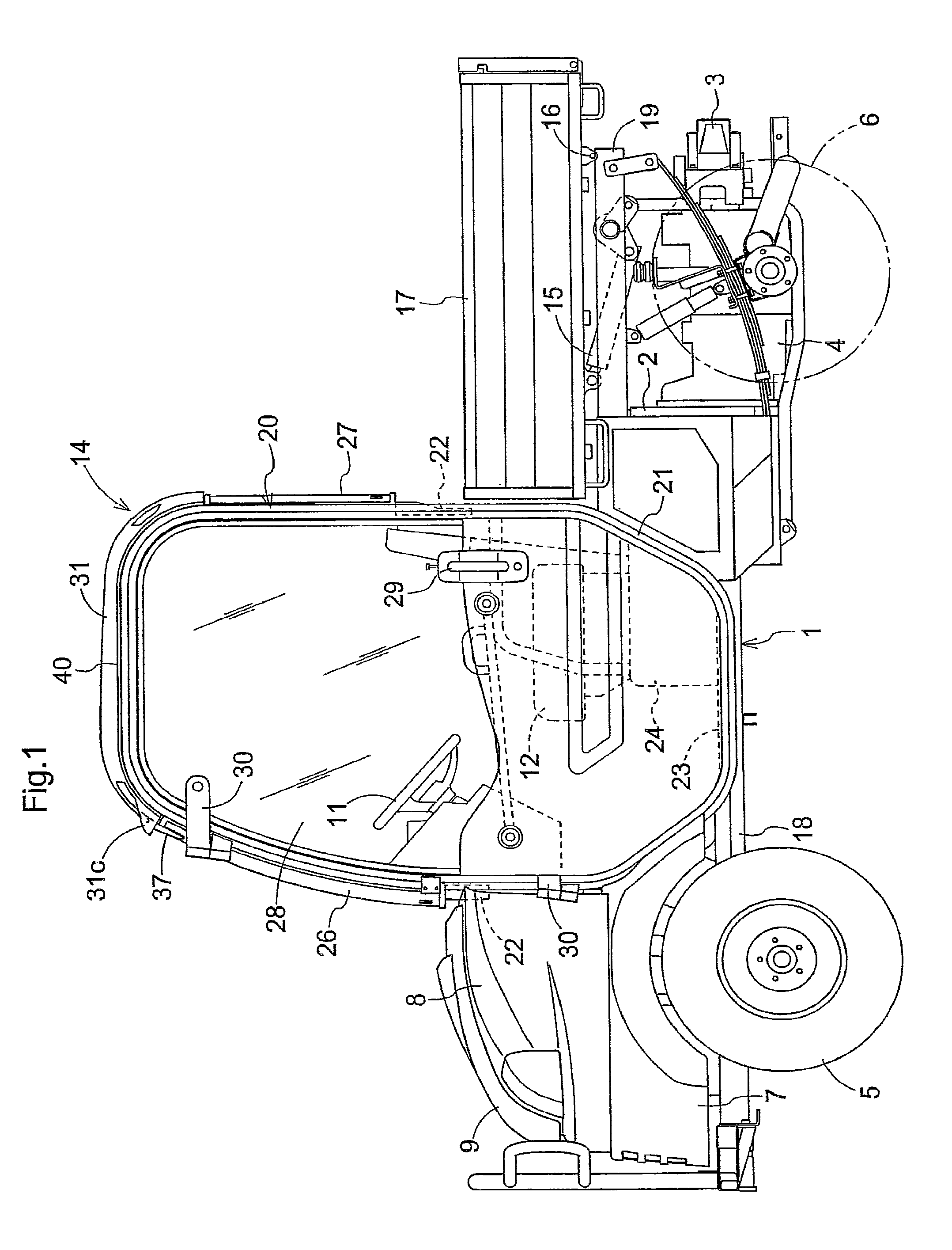
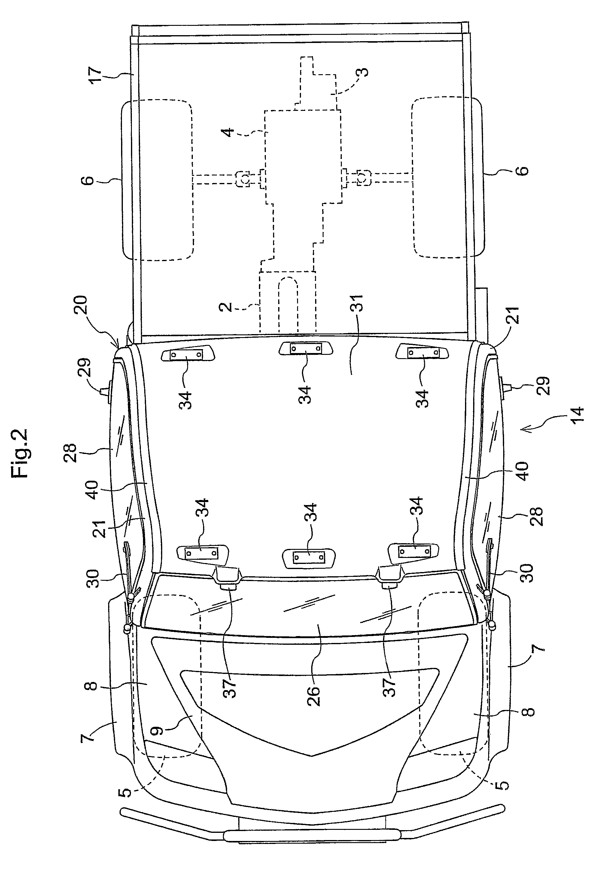
[0067]In the above embodiment, the invention is applied to the seal structure of the cab 14 of the utility vehicle shown as an example of working vehicles. The invention is equally applicable to the seal structure of cabs 14 of other types of working vehicle, e.g. agricultural working vehicles such as tractors and combines, and construction working vehicles such as backhoes and wheel loaders.


PUM


Abstract

A cab includes a cab frame forming the cab, an outer roof configured to cover the cab frame from above and to be fastened to the cab frame from above, a seal mount protruding downwardly from an edge of the outer roof, and a seal material including a body portion having a recess for receiving the seal mount. The periphery of the body portion of the seal material has a seal lip for contacting the cab frame for sealing, and a drain groove for draining water entering between the seal material and the cab frame.

Description

BACKGROUND OF THE INVENTION[0001]This invention relates to a cabin, and more particularly to a seal structure for a vehicle cabin.[0002]A known seal structure for a cabin (referred to as cab), as disclosed in JP 8-133123, for example, has an outer roof tightened from above to a cab frame through a seal member to seal a gap between the outer roof and cab frames. Another known seal structure for a cab, as disclosed in JP 11-91639, a seal material is fitted in an elastically deformed state between a peripheral portion of a top board and a top board support to seal a gap between the top board and a cab frame.[0003]In the conventional seal structure for a cab disclosed in JP 8-133123, the outer roof is tightened and fixed from above, and its tightening force presses the seal member on the cab frame, thereby securing sealing performance between the outer roof and cab frame. However, the seal member performs sealing action in only one location. When, for example, the seal member becomes de...

Claims


Application Information

Patent Timeline
Patent Type & Authority Patents(United States)
IPC IPC(8): B60R13/07
CPCB62D25/07B62D33/06
Inventor NAKAMURA, NORIMISAJI, SHINICHIROTSUCHIYA, TAKESHIFUJINO, MASANORI
Owner KUBOTA LTD
Why Eureka
Try Eureka