Method and apparatus for parallel engine generators

a technology of parallel engine and generator, which is applied in the direction of emergency power supply arrangements, transmission systems, transportation and packaging, etc., can solve the problems of comparatively more expensive than non-parallel systems and the costly nature of such systems, and achieve the effect of reducing the installation and maintenance costs of parallel systems

Active Publication Date: 2010-10-19
ASCO POWER TECH LP
View PDF5 Cites 59 Cited by
  • Summary
  • Abstract
  • Description
  • Claims
  • Application Information

AI Technical Summary

Benefits of technology

[0011]Thus, it is desirable to provide a paralleling method and system that may be provided as a pre-packaged or single-package solution. Therefore, a method of paralleling engine generators is presented. The presented method may be a single-package solution, enabling multiple, paralleled engine generators to provide power to an emergency power bus. In addition, and as a consequence of being a single-package solution, installation and maintenance costs associated with a paralleling system may be reduced.

Problems solved by technology

Generally speaking, the system 10 and similar systems are usually custom designed and built, and due to complexity, they are comparatively more expensive than non-parallel systems.
The costly nature of such systems may be attributed to installation and maintenance costs.

Method used


Image

  • Method and apparatus for parallel engine generators
  • Method and apparatus for parallel engine generators
  • Method and apparatus for parallel engine generators

Examples


Embodiment Construction

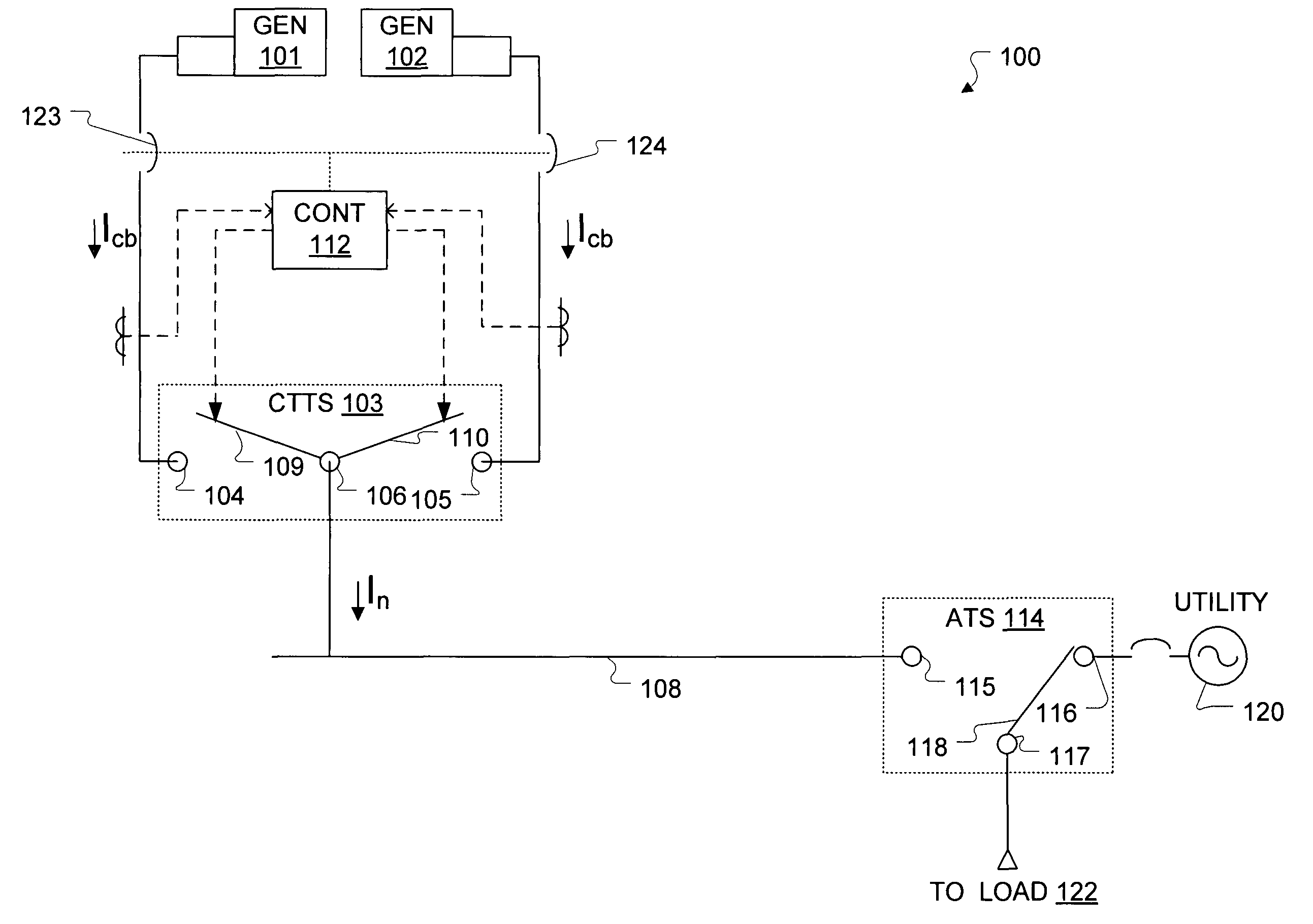
[0024]Turning now to the Figures, FIG. 3A is a schematic diagram of a first arrangement of an engine generator paralleling system 100. The system 100 comprises engine generators 101, 102 coupled to a CTTS 103. The CTTS 103 includes input terminals 104, 105, which are respectively coupled to receive a first power from the generator 101 and a second power from the generator 102. The CTTS 103 also includes a load output 106 that is coupled to a power bus 108. Within the CTTS 103 are switches 109, 110, that may be toggled so that each of the inputs 104, 105 may be routed to the load output 106. To open and close the switches 109, 110, the system 100 further includes a system controller 112 communicatively coupled to the CTTS 103.

[0025]Coupled to the power bus 108 is an ATS 114. The ATS 114 includes an emergency power input 115, a utility power input 116, a load output 117, and a switch 118. The input 115 is coupled to the power bus 108, the input 116 is coupled to a utility power source...


PUM


Abstract

A method and apparatus for paralleling engine generators. One or more closed transition transfer switches (CTTSes) are coupled to two or more engine generators. A system controller is programmed to operate the one or more CTTSes so that each of the generators provides an emergency power and so that the generators may simultaneously supply emergency power to the power bus.

Description

BACKGROUND[0001]1. Field of the Invention[0002]The present application is generally directed to a method and apparatus for operating at least two engine generators in parallel. More particularly, the present application is directed to a method and / or apparatus for operating a closed transition transfer switch (CTTS), such as those used in “make-before-break” emergency power applications, to enable parallel operation of at least two generators. However, aspects of the present application may be equally applicable in other scenarios as well.[0003]2. Description of Related Art[0004]A general diagram of a conventional engine generator paralleling system 10 is illustrated in FIG. 1. The system 10 may be used to power an emergency power bus 12 with three engine generators 13-15. As can be seen from FIG. 1, the system 10 comprises three separate circuit breakers 16-18 coupled to the power bus 12 and the generators 13-15. The power bus 12 is coupled to transfer switches 19-21. The transfer ...

Claims


Application Information

Patent Timeline
Patent Type & Authority Patents(United States)
IPC IPC(8): H02J7/00H02J9/00
CPCH02J3/40H02J9/066Y10T307/615
Inventor YAGUDAYEV, BORIS M.PETRO, JACKESCOTT, BRIAN J.BEGAUER, KENNETH D.
Owner ASCO POWER TECH LP
Why Eureka
Try Eureka