Electroacoustic transducer mounting in shells of hearing prostheses

a technology of electroacoustic transducers and hearing prostheses, which is applied in the direction of electric transducers, electrical apparatus, specific frequency response details, etc., can solve the problems of difficult correct placement of resilient suspensions, limited space inside the hearing aid shell to accommodate resilient suspensions, and inability to meet the requirements of space requirements, etc., to achieve the effect of fast and easy assembly and assembly

Inactive Publication Date: 2010-10-26
SONION NEDERLAND
View PDF12 Cites 88 Cited by
  • Summary
  • Abstract
  • Description
  • Claims
  • Application Information

AI Technical Summary

Benefits of technology

[0013]Thus, an assembly has been invented in which the acoustic path, normally denoted the front chamber, between the sound outlet and the diaphragm or membrane may be a standard front chamber, but in which the back chamber, which is the normal phrase for the acoustic chamber or path connected to the other side of the diaphragm, now also includes at least part of the compartment in which the miniature loudspeaker is positioned. Thus, the miniature loudspeaker has more than one sound path from its interior to the exterior thereof, one path comprising the sound outlet and one or more others connecting (acoustically) the interior of the miniature loudspeaker with the interior of the housing. This provides a number of degrees of freedom in that the volume and acoustic properties of the back chamber may be varied within wider limits than what was possible within the dimensions normally available in miniature loudspeakers.
[0078]Also, in any of the first, third and fifth embodiments, the housing may be a customized ITE / ITC / CIC housing. These housings must have very small dimensions of the parts positioned in the ear canal of the user. The present invention facilitates the providing of very small communication devices.

Problems solved by technology

One problem associated with the above-mentioned hearing aid construction techniques is the space requirement inside the hearing aid shell to accommodate the resilient suspension and flexible leads.
In small hearing aids such as the ITE type of hearing aids and in particular in ITC (in the canal) and CIC (completely in-the-canal) type of hearing aids, the available space for the resilient suspension at a tip of the hearing aid shell is typically very limited since the shell tip must be dimensioned for placement deeply inside the ear canal of the user or patient.
Another problem is that even if adequate space for the resilient suspension is available at the tip of the hearing aid shell, the correct placement of the resilient suspension can be very difficult and therefore time consuming for the assembly technician because it must be ensured that the resiliently suspended receiver is allowed substantially unrestricted vibration does not contact the walls of the hearing aid shell.
Finally, the correct placement of the resiliently suspended receiver is subjected to additional difficulties by the presence of the pair of flexible electrical leads which tends to pull or push the receiver away from the correct position due to the stiffness of the leads and the low weight and resilient suspension of the receiver.
These problems are firstly encountered during manufacture of the hearing aid but, unfortunately, resurface if the hearing aid receiver malfunctions or fails in the field and needs replacement in a service and repair shop.
This is, unfortunately, a very common situation because the receiver is placed at a very exposed position deeply inside in the user's ear canal where it is subjected to moisture and cerumen contamination.
In this latter repair situation, it may be an even more difficult task for the service technician to ensure correct positioning of the replacement receiver inside its resilient suspension and the shell part(s) because he may lack adequate instructions, measurement equipment or training to complete the task.
Furthermore, in prior art ITE hearing aids, the receiver has only been replaceable from a rear portion or so-called faceplate portion of the aid where a substantially plane pre-manufactured plastic plate has been glued to the upper circumferential portion of the hearing aid shell so as to isolate the interior of the hearing aid from the surrounding environment.
Accordingly, to replace the defective receiver, the faceplate portion of the aid had to be re-opened with a substantial risk of damaging the customized ITE shell and / or mechanical or electronic components housed within the shell.

Method used


Image

  • Electroacoustic transducer mounting in shells of hearing prostheses
  • Electroacoustic transducer mounting in shells of hearing prostheses
  • Electroacoustic transducer mounting in shells of hearing prostheses

Examples


Embodiment Construction

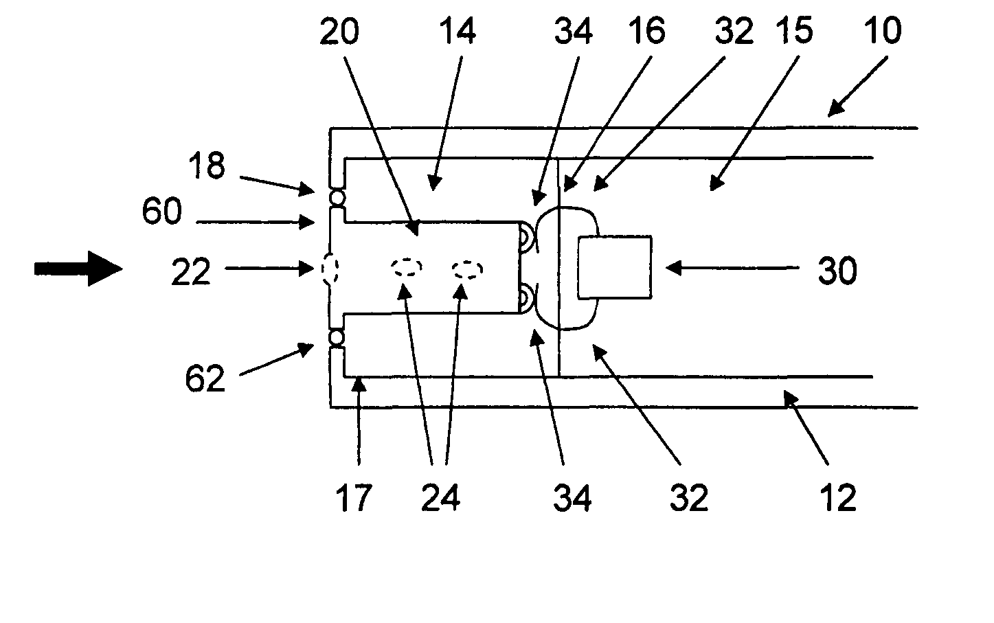
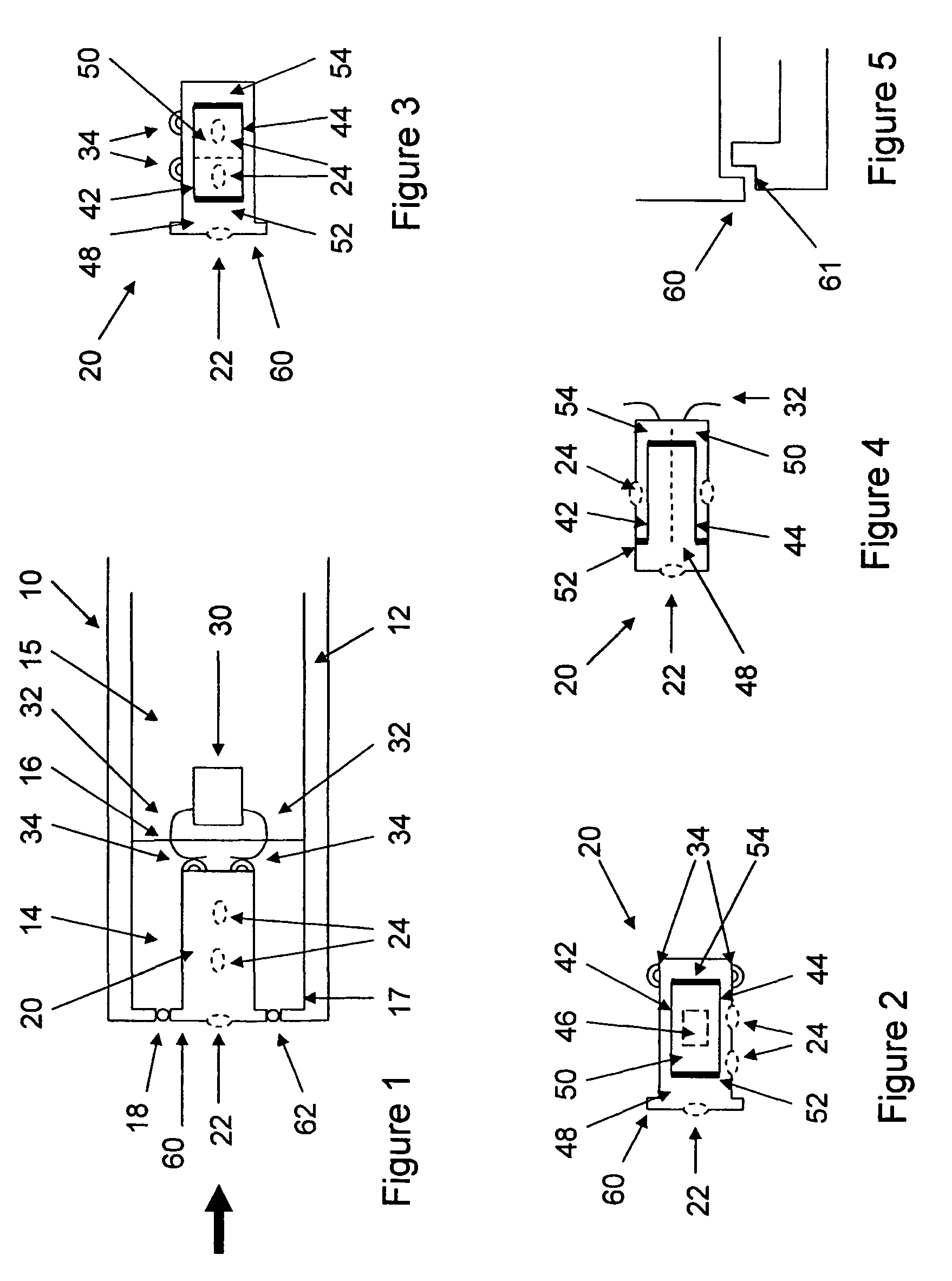
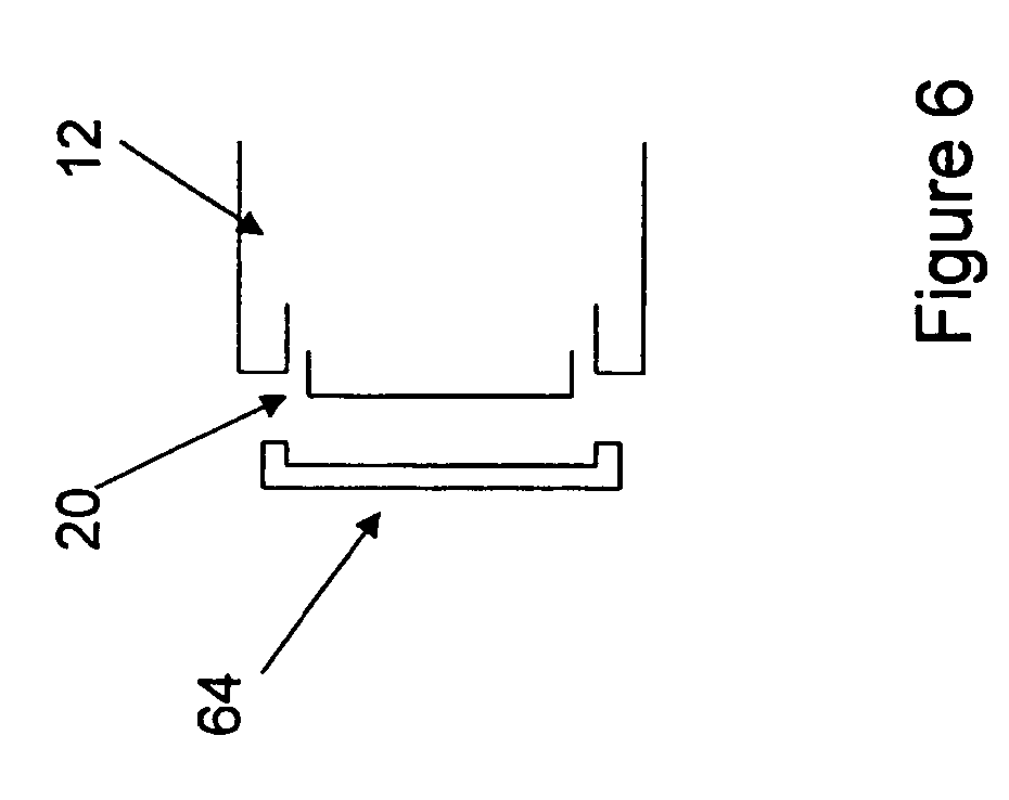
[0101]In FIG. 1, the overall structure of a preferred embodiment of a personal communication device 10 is seen, having a housing 12 in which is mounted a hearing aid receiver or loudspeaker 20.

[0102]The present invention is able to reduce the overall dimensions of the system so that it is useful in CIC, ITE, and ITC hearing aids.

[0103]The housing 12 has an inner space that is divided into first and second inner compartments 14 and 15, respectively. The first inner compartment 14 is delimited by the housing walls 17 and an intermediate wall 16 providing an acoustic sealing between the compartments 14 and 15. The transducer element 20 is mounted in the space 14 so as to close or seal an opening 18 in the housing 12.

[0104]The transducer element 20 is adapted to receive or generate sound and has a sound inlet / outlet 22 exposed to the surroundings of the hearing aid 10 in the sound inlet / outlet port or opening 18.

[0105]The inner structure of the hearing aid receiver or transducer element...


PUM


Abstract

A hearing aid and a receiver for use therein, the receiver being tip-mountable in a chamber of a housing. The back chamber of the receiver is acoustically connected to the chamber of the housing. The receiver is a dual-diaphragm receiver providing no or very little vibrations, whereby the receiver is fixedly but removably mounted to the housing. Electrical connections are provided between the receiver and housing using solderless, biasing electrical contacts, whereby removal of the receiver is facilitated.

Description

[0001]This application claims the benefit of U.S. Provisional Application No. 60 / 642,641, filed Jan. 10, 2005.FIELD OF INVENTION[0002]The present invention relates to improvements in personal communication devices, such as hearing aids or in-ear monitors, and especially in miniature hearing aids or in-ear monitors, such as ITE / CIC / ITC hearing aids or monitors, which require extremely small components and which need to be adapted to the dimensions of the ear canal of the user.BACKGROUND OF THE INVENTION[0003]Hearing aid receivers or loudspeakers have conventionally been mounted in both BTE (behind the ear) and ITE (in the ear) hearing aids with the use of resilient suspensions to suppress or attenuate mechanical vibrations of the receivers and prevent that these were transmitted to a microphone of the hearing aid. Due to the requirements of very large acoustical gain between proximately located microphone and receiver components, the utilization of the resilient suspension has been r...

Claims


Application Information

Patent Timeline
Patent Type & Authority Patents(United States)
IPC IPC(8): H04R25/00
CPCH04R9/063H04R11/02H04R25/48H04R25/604H04R25/456H04R2209/026B33Y80/00
Inventor VAN HALTEREN, AART ZEGER
Owner SONION NEDERLAND
Why Eureka
Try Eureka