
Cover for mobile communication terminal, and mobile communication terminal

a mobile communication terminal and cover technology, applied in the field of cover for a mobile communication terminal, can solve the problems of loss of the functionality of the mobile communication terminal, the side wall surface cannot be seen from the exterior, and the cover position deviated from its proper covering position, etc., to achieve the effect of soft texture, high quality and the same operating feeling

Inactive Publication Date: 2010-10-26
VODAFONE GRP PLC
View PDF20 Cites 9 Cited by
  • Summary
  • Abstract
  • Description
  • Claims
  • Application Information

AI Technical Summary

Benefits of technology

"The present invention provides a cover for a mobile communication terminal that is made from a flexible material and can cover the side wall surface where the information input-output portion is located. This cover can prevent the cover from deviating from its proper position and interfering with the operation of the mobile communication terminal. The cover can also provide a soft texture and a high-quality feel to the user. Additionally, the invention provides a second cover that can be attached to the mobile communication terminal using a fixing panel or a fastener, making it easy to integrate the cover with the mobile communication terminal. The cover can also be designed to fold up or rotate, allowing for easy insertion and removal. Overall, the invention ensures that the mobile communication terminal and the cover are a single unit, providing a seamless and comfortable user experience."

Problems solved by technology

If a cover made from a flexible substance for absorbing shock is fitted to a mobile communication terminal, then, as described above, it can easily deviate from its proper covering position, and there has been a possibility of loss of the functionality of the mobile communication terminal.
Moreover, “covering a side wall surface” means being in the state of covering all of the side wall surface, so that the side wall surface cannot be seen from the exterior.

Method used


Image

  • Cover for mobile communication terminal, and mobile communication terminal
  • Cover for mobile communication terminal, and mobile communication terminal
  • Cover for mobile communication terminal, and mobile communication terminal

Examples


first embodiment

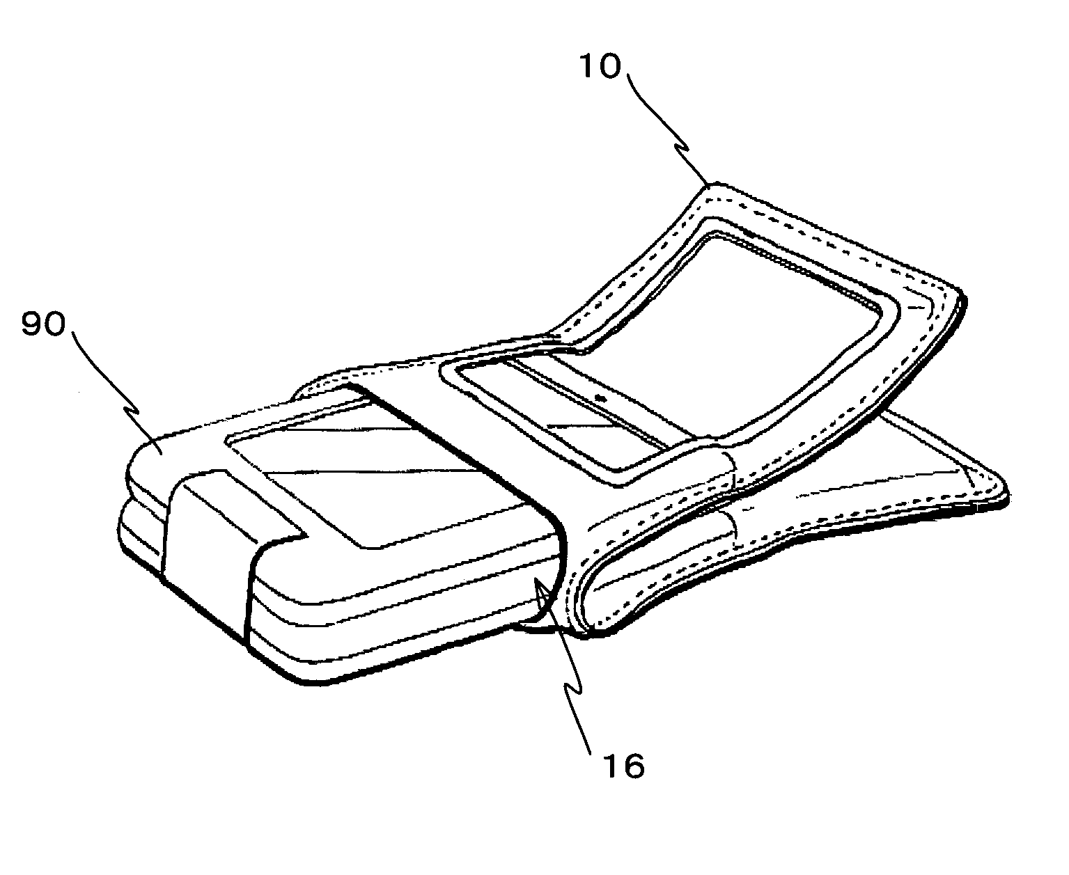
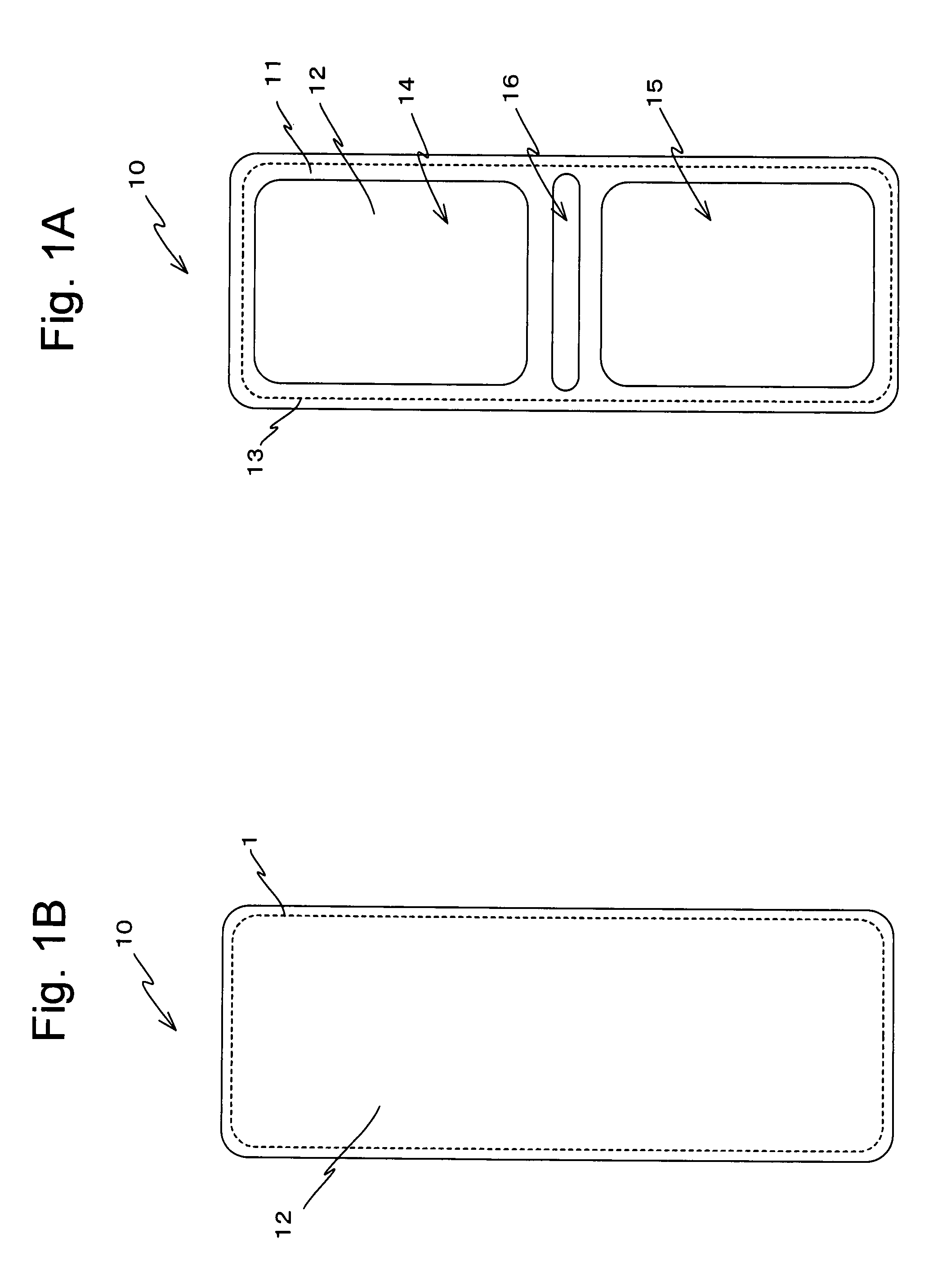
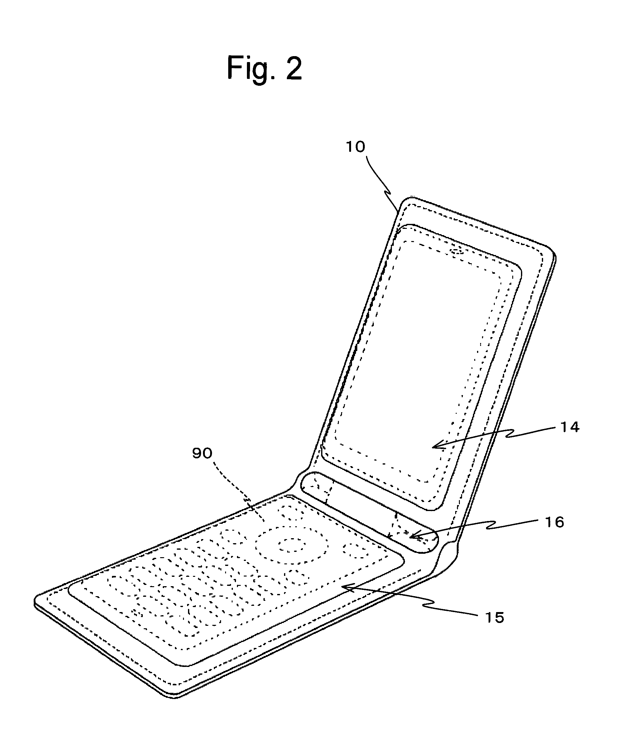
[0051]In FIG. 1A there is shown an elevation view of a cover 10 for a portable telephone according to the present invention (hereinafter simply referred to as the “cover 10”), and a rear view of this cover 10 is shown in FIG. 1B. As shown in FIGS. 1A and 1B, this cover 10 is made by stitching together, by a seam 13, two pieces of leather: a front surface leather portion 11 and a rear surface leather portion 12. Moreover, as shown in FIG. 1A, on the front surface leather portion 11 of this cover 10, there are formed (i) a display surface opening portion 14 for exposing a display screen of a display device of the portable telephone; (ii) an operation surface opening portion 15 for exposing an operating surface of an input device of the portable telephone; and (iii) an fitting opening portion 16 for fitting this cover 10 onto the portable telephone.

[0052]In FIG. 2, the cover 10 is shown in the state of having been fitted upon the portable telephone 90. In this case, the portable teleph...

second embodiment

[0063]In the following, the present invention will be explained with reference to FIGS. 8A through 10.

[0064]FIG. 8A shows an elevation view of a cover 20 for a portable telephone (hereinafter simply termed the “cover 20”) according to a second embodiment of the present invention; and FIG. 8B shows a rear view of this cover 20. As shown in FIGS. 8A and 8B, this cover 20 is manufactured by stitching together, by seams 24 and 25, three pieces of leather: a display surface front surface leather portion 21, an operating surface front surface leather portion 22, and a rear surface leather portion 23. Furthermore, as shown in FIG. 8A, the display surface front surface leather portion 21 of the cover 20 comprises a display surface opening portion 26 for exposing the display screen of the display device of the portable telephone 90, while the operating surface front surface leather portion 22 comprises an operating surface opening portion 27 for exposing an operating surface of an input devi...

third embodiment

[0071]In the following, the present invention will be explained with reference to FIGS. 11A through 13.

[0072]FIG. 11A shows an elevation view of a cover 30 for a portable telephone according to the third embodiment of the present invention (hereinafter simply termed the “cover 30”), and FIG. 11B shows a rear view of this cover 30. As shown in FIGS. 11A and 11B, this cover 30 is manufactured by stitching together two pieces of leather, a front surface leather portion 31 and a rear surface leather portion 32, with a seam 35, except for a portion on their right side surfaces. The right side surface of the cover 30 is a fitting fastener portion 37, in which a fastener which can be opened and closed for fitting the cover 30 over the portable telephone is stitched with seams. Furthermore, as shown in FIG. 11A, the front surface leather portion 31 of the cover 30 is provided with a display surface opening portion 33 for exposing a display screen of a display device of the portable telephon...


PUM


Abstract

In a front surface leather portion of a cover 10, there are formed a display surface opening portion 14 for exposing a display screen of a display of a mobile communication terminal 90, an operating surface opening portion 15 for exposing an operating surface of an input device of the terminal 90, and a fitting opening portion 16 for fitting this cover 10 to the terminal 90. Accordingly, even when the cover 10 is fitted, it is possible for the user both to check the display screen of the terminal 90 from the portion 14 and to actuate the input device of the terminal 90 from the portion 15. Due to this, it is possible to implement a cover for a mobile communication terminal which, along with maintaining a good operating feeling and serving as cushioning material in the case of shock, can also impart a soft texture and a sense of high quality.

Description

RELATED APPLICATION[0001]This is a continuation application of the international patent application No. PCT / JP2006 / 300609 filed with Application date: Jan. 18, 2006. The present application is based on, and claims priority from, J.P. Application 2005-01007, filed on Jan. 18, 2005, the disclosure of which is hereby incorporated by reference herein its entirety.BACKGROUND OF THE INVENTION[0002]The present invention relates to a cover for a mobile communication terminal and to a mobile communication terminal, and more particularly relates to a cover for a mobile communication terminal which is integrated with a mobile communication terminal, and to a mobile communication terminal to which such a cover for a mobile communication terminal can be fitted.BACKGROUND ART[0003]In the prior art, mobile communication terminals, such as, among others, cellular phones, have become widespread. With such mobile communication terminals, with regard to elements based upon internal functions such as w...

Claims


Application Information

Patent Timeline
Patent Type & Authority Patents(United States)
IPC IPC(8): H04M1/00A45C11/00A45C13/02H04M1/11
CPCA45C11/00H04B1/3888H04M1/0283H04M1/0214
Inventor URAMOTO, YOSHIHIRODAIDO, SHINENOMOTO, NOBUYUKIASADA, FUJI
Owner VODAFONE GRP PLC
Learn More