Vehicular illumination device

a technology of illumination device and vehicle, which is applied in the direction of lighting support device, transportation and packaging, lighting and heating apparatus, etc., can solve the problem of end of light distribution control and achieve the effect of controlling chattering

Inactive Publication Date: 2010-11-02
TOYOTA JIDOSHA KK
View PDF14 Cites 7 Cited by
  • Summary
  • Abstract
  • Description
  • Claims
  • Application Information

AI Technical Summary

Benefits of technology

[0008]The present invention has been made in consideration of the circumstances described above, and an object of the present invention is to suppress chattering of light distribution control and prevent a load increase of light distribution control.
[0013]When the illumination object that was detected by the detection unit ceases to be detected, the judgment unit judges whether or not it is necessary to maintain the light distribution alteration control of the vehicular illumination unit by the light distribution control unit in a current state. If the judgment unit determines that it is necessary to maintain the light distribution alteration control in the current state, the control unit controls the light distribution control unit such that the light distribution alteration control by the light distribution control unit is maintained in the current state. That is, it is judged by the judgment unit whether or not it is to maintain light distribution alteration control of the vehicular illumination unit in the current state, and light distribution control is implemented. As a result, chattering of control due to the light distribution control being carried out can be prevented. Thus, since control chattering can be prevented, a load increase in the light distribution control can be suppressed.
[0014]For example, the judgment unit may judge that there is a need to maintain the alteration control by the light distribution control unit in the current state when a vertical movement of the subject vehicle is detected by a vertical movement detection unit, which detects a vertical movement of the subject vehicle. Accordingly, when vertical movement of the vehicle which is equal to or greater than a predetermined value is caused due to the vehicle driving over a step in a road surface, because the current light distribution control state is maintained, chattering that would otherwise occur when driving over a road surface step can be prevented.
[0016]Further, the judgment unit may be configured so as to make a judgment such that there is a need to maintain the alteration control by the light distribution alteration unit in the current state when the vertical movement detection units detects that a vertical movement of the subject vehicle exceeds a predetermined range (for example, a predetermined range, a detection range of the detection unit or the like). With such a configuration, light distribution alteration control is performed within a range in which the detection unit can perform detection so that the current light distribution is maintained only when the detection range is exceeded, whereby control chattering can be prevented while securing alteration control in a required range.

Problems solved by technology

However, with the technology described in JP-A No. 2006-21631, when a non-subject or an opposing vehicle is identified and light distribution control is being performed, if the subject vehicle drives over a step in a road surface, then the subject vehicle is tilted on the way, and thus the opposing vehicle temporarily falls outside a detection range of the camera so that the light distribution control is ended.

Method used


Image

  • Vehicular illumination device
  • Vehicular illumination device
  • Vehicular illumination device

Examples


Embodiment Construction

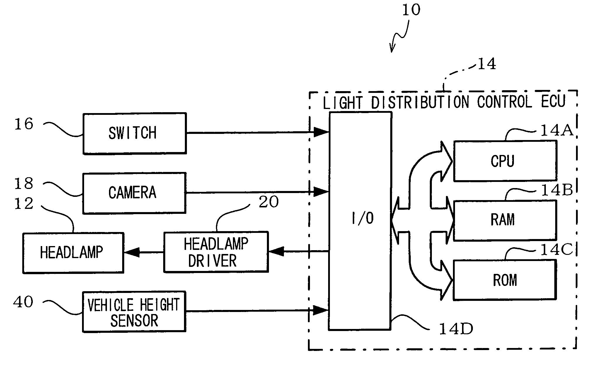
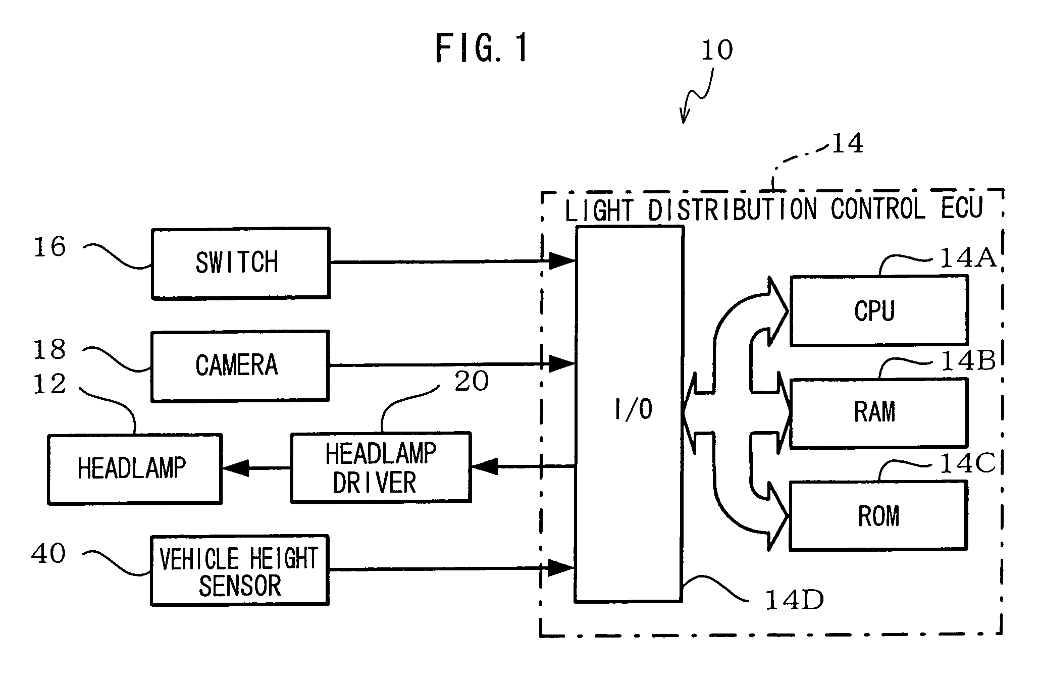
[0025]Herebelow, an example of an embodiment of the present invention will be described in detail with reference to the drawings. FIG. 1 is a block diagram showing a structure of a vehicular illumination device relating to an embodiment of the present invention.

[0026]In a vehicular illumination device 10 relating to the embodiment of the present invention, as shown in FIG. 1, a headlamp 12 provided at a vehicle is connected to a light distribution control ECU 14, and lighting and extinguishing of the headlamp 12 are controlled by the light distribution control ECU 14.

[0027]In the present embodiment, the light distribution control ECU 14 carries out light distribution control so as to extinguish, of light distribution regions of the headlamp 12, a region corresponding to a non-subject vehicle such as an opposing vehicle in front.

[0028]The light distribution control ECU 14 is structured by a microcomputer including a CPU 14A, a RAM 14B, a ROM 14C and an I / O 14D.

[0029]A table for imple...


PUM


Abstract

A vehicular illumination device includes a light distribution control unit, a determination unit and a control unit. The light distribution control unit performs an alteration control of a vehicular illumination unit so as to alter a light distribution with respect to an illumination object detected by a detection unit. When the illumination object ceases to be detected, the determination unit determines whether or not there is a need to maintain the alteration control in a current state. When it is determined that there is a need to maintain the alteration control in the current state, the control unit controls the light distribution control unit so as to maintain the alteration control in the current state.

Description

CROSS-REFERENCE TO RELATED APPLICATION[0001]This application claims priority under 35 USC 119 from Japanese Patent Application No. 2006-337997, the disclosure of which is incorporated by reference herein.BACKGROUND[0002]1. Technical Field[0003]The present invention relates to a vehicular illumination device, and more particularly to a vehicular illumination device which controls a light distribution of a headlamp or the like.[0004]2. Related Art[0005]A technology described in, for example, Japanese Patent Application Laid-Open (JP-A) No. 2006-21631 has been proposed as a vehicular illumination device for controlling a light distribution of a headlamp or the like.[0006]The technology described in JP-A No. 2006-21631 proposes the provision of: a plurality of light sources that illuminate respectively different regions and form a predetermined light distribution pattern, the whole of which includes a main light distribution region and a peripheral light distribution region; a camera th...

Claims


Application Information

Patent Timeline
Patent Type & Authority Patents(United States)
IPC IPC(8): B60Q1/00
CPCB60Q1/085B60Q1/143B60Q2300/056B60Q2300/45B60Q2300/324B60Q2300/41B60Q2300/42B60Q2300/132
Inventor WATANABE, SHINYA
Owner TOYOTA JIDOSHA KK
Why Eureka
Try Eureka