Advanced power recovery and energy conversion systems and methods of using same

a power recovery and energy conversion technology, applied in the field of heat recovery, can solve the problems of high inefficiency of heat recovery at low operating temperature differences, complex process, and inability to meet the requirements of operation, etc., and achieve the effect of limiting the efficiency of heat recovery

Active Publication Date: 2010-11-09
TAS ENERGY +1
View PDF35 Cites 32 Cited by
  • Summary
  • Abstract
  • Description
  • Claims
  • Application Information

AI Technical Summary

Problems solved by technology

This process is complex and requires either multiple steam turbines or a multi-stage steam turbine, feed water heaters, steam drums, pumps, etc.
The system remains complex and is highly inefficient at low operating temperature differences.
The four largest weaknesses of the prior art system are a) the vapor 107 discharged from the second turbine 124 is significantly superheated and thereby the system of FIG. 10 fails to recover a portion of the valuable heat, b) the system utilizes a subcritical working fluid which limits the efficiency of the heat recovery in the heat recovery heat exchangers 120 and 121 due to the non-linearity of the temperature-enthalpy profile in said exchangers, c) the system generates unnecessary entropy further reducing its output in accordance with the Second Law of Thermodynamics, and d) the complexity of the system having multiple turbines and multiple heat recovery heat exchangers is reflected in an increased cost of the system for a given capacity. recovery heat exchanger(s) are usually the largest costs in a system of the type.

Method used


Image

  • Advanced power recovery and energy conversion systems and methods of using same
  • Advanced power recovery and energy conversion systems and methods of using same
  • Advanced power recovery and energy conversion systems and methods of using same

Examples


Embodiment Construction

[0034]Illustrative embodiments of the invention are described below. In the interest of clarity, not all features of an actual implementation are described in this specification. It will of course be appreciated that in the development of any such actual embodiment, numerous implementation-specific decisions must be made to achieve the developers' specific goals, such as compliance with system-related and business-related constraints, which will vary from one implementation to another. Moreover, it will be appreciated that such a development effort might be complex and time-consuming, but would nevertheless be a routine undertaking for those of ordinary skill in the art having the benefit of this disclosure.

[0035]The present invention will now be described with reference to the attached drawings which are included to describe and explain illustrative examples of the present invention. The words and phrases used herein should be understood and interpreted to have a meaning consistent...


PUM


Abstract

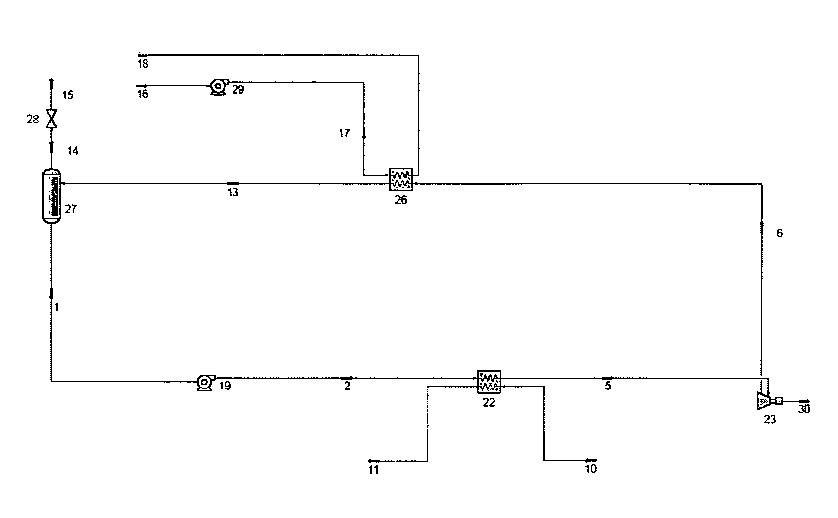
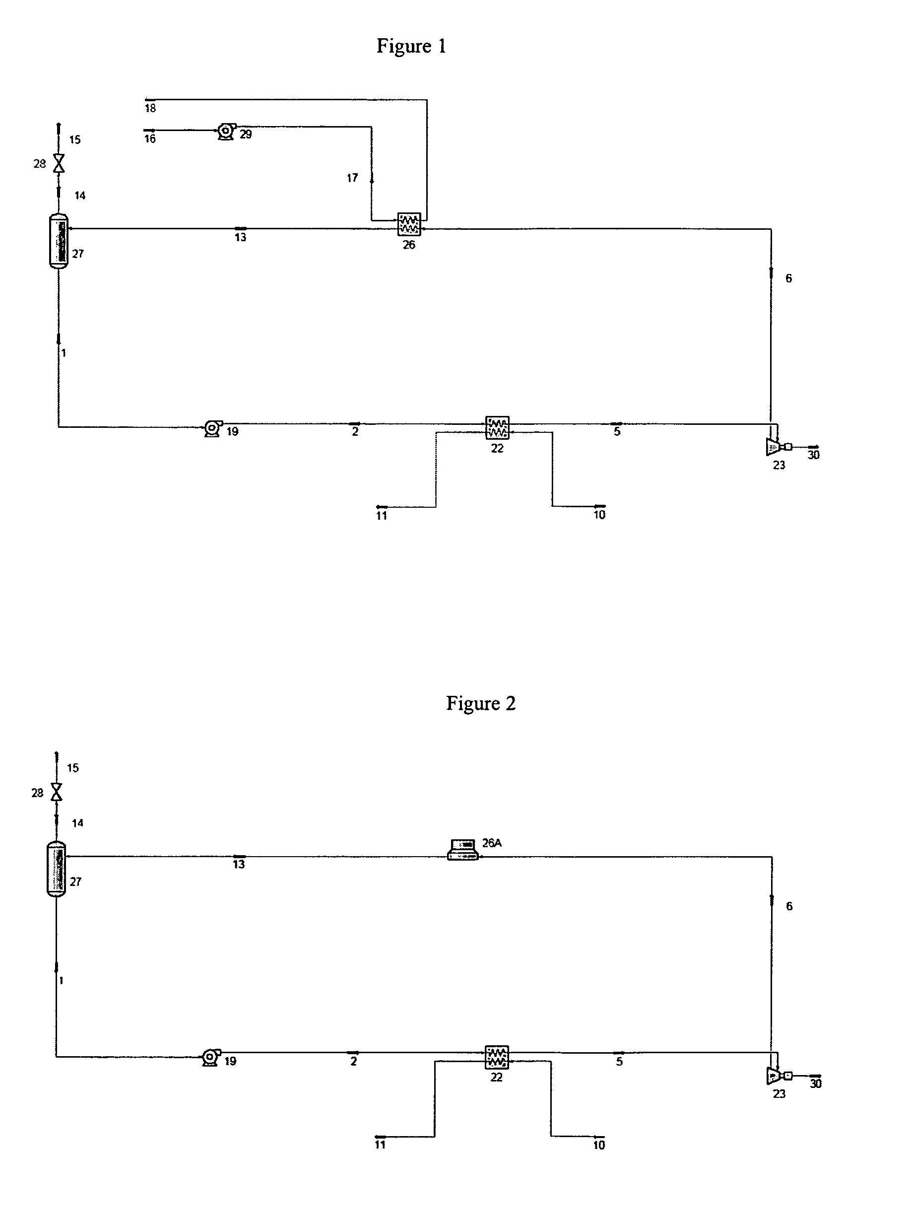
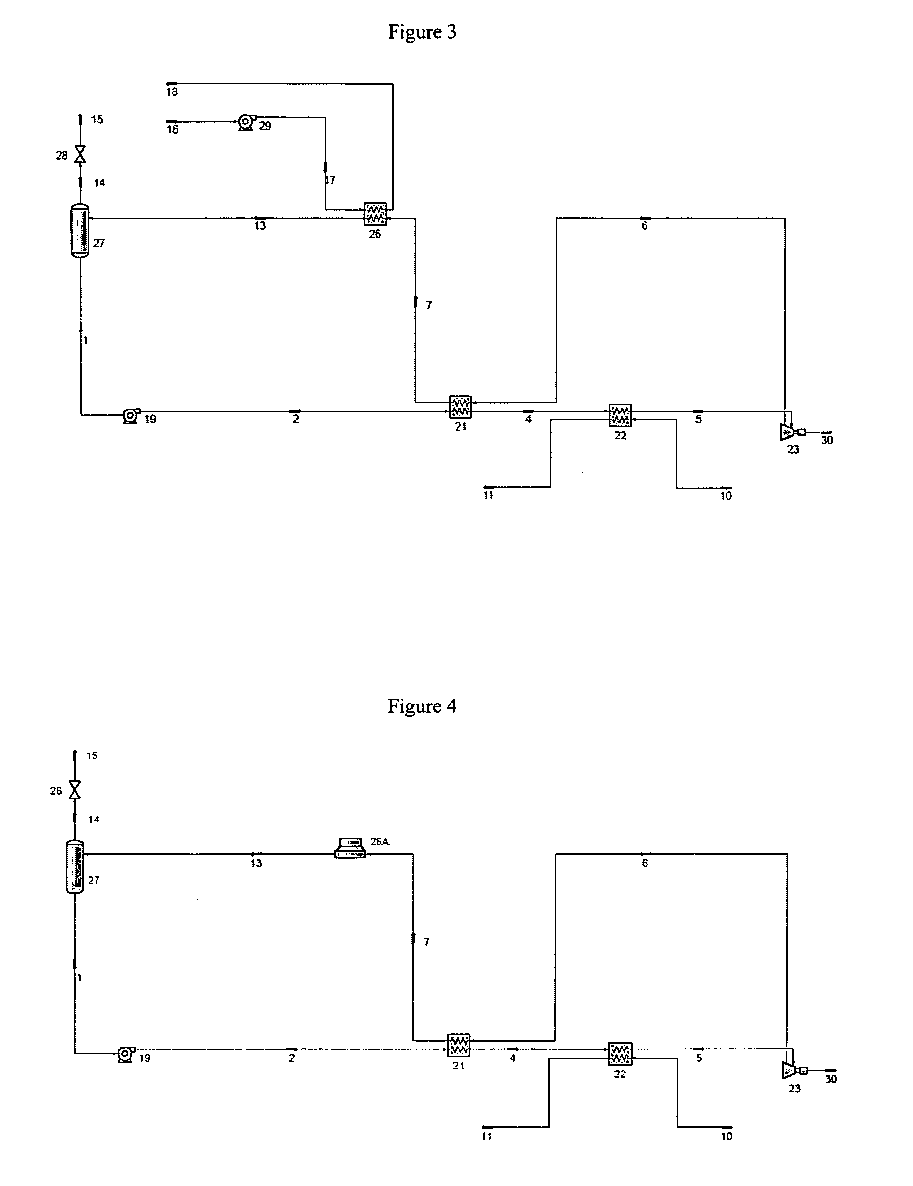
Disclosed herein are various systems and methods for producing mechanical power from a heat source. The system may include a heat recovery heat exchanger, a turbine, a condenser heat exchanger, and a liquid circulating pump, etc. In other embodiments, a desuperheater or an economizer, or both, may be employed. In one illustrative embodiment, the system comprises a first heat exchanger adapted to receive a fluid from a heat source and a working fluid, wherein, when the working fluid is passed through the first heat exchanger, the working fluid is converted to a vapor via heat transfer with the fluid from the heat source, at least one turbine adapted to receive the vapor, and an optional economizer heat exchanger adapted to receive exhaust vapor from the turbine and the working fluid, wherein a temperature of the working fluid is adapted to be increased via heat transfer with the exhaust vapor from the turbine prior to the introduction of the working fluid into the first heat exchanger. The system further comprises a condenser heat exchanger that is adapted to receive the exhaust vapor from the turbine after the exhaust vapor has passed through the optional economizer heat exchanger and a cooling fluid, wherein a temperature of the exhaust vapor is reduced via heat transfer with the cooling fluid, and a pump that is adapted to circulate the working fluid to the optional economizer heat exchanger.

Description

BACKGROUND OF THE INVENTION[0001]1. Field of the Invention[0002]The present invention generally relates to heat recovery for the purpose of electrical or mechanical power generation. Specifically, the present invention is directed to various systems and methods for the conversion of heat of any quality into mechanical or electrical power.[0003]2. Description of the Related Art[0004]In general, there is a constant drive to increase the operating efficiency of heat and power recovery systems. By increasing the efficiency of such systems, capital costs may be reduced, more power may be generated and there may be a reduction of possible adverse impacts on the environment, e.g., a reduction in the amount of waste heat that must ultimately be absorbed by the environment. In other industrial processes, an excess amount of heat may be generated as a byproduct of the process. In many cases, such waste heat is normally absorbed by the environment through the use of waste heat rejection device...

Claims


Application Information

Patent Timeline
Patent Type & Authority Patents(United States)
IPC IPC(8): F01K7/34
CPCF01K3/14F01K3/265
Inventor PIERSON, TOM L.PENTON, JOHN DAVID
Owner TAS ENERGY
Why Eureka
Try Eureka