Differential gear unit

a gear unit and gear technology, applied in the direction of gearing details, gearing, transportation and packaging, etc., can solve the problems of a different type of gear unit that cannot withstand a large driving force, and achieve the effects of suppressing the increase in size and weight, high strength, and long fatigue li

Active Publication Date: 2010-11-09
TOYOTA JIDOSHA KK
View PDF21 Cites 5 Cited by
  • Summary
  • Abstract
  • Description
  • Claims
  • Application Information

AI Technical Summary

Benefits of technology

[0012]In light of the above-mentioned circumstances, the invention is made in order to solve these problems. It is therefore an object to provide a differential gear unit which can withstand a large driving force, and which makes it possible to minimize increases in weight and size thereof.
[0013]Therefore, according to an aspect of the invention, there is provided a differential gear unit which divides a driving force input therein into a first output and second output and which permits a difference between a rotational speed of the first output and a rotational speed of the second output The differential gear unit includes a casing which defines an internal space and an opening communicated with the internal space, and which is rotatable in a given direction and in a direction opposite to the given direction. The casing includes an input portion in which a driving force is input. In the differential gear unit according to the aspect, the casing is configured such that the fatigue life of the casing when the driving force is repeatedly input in the input portion in the given direction is longer than that when the driving force is repeatedly input in the input portion in the direction opposite to the given direction.
[0014]In the thus configured differential gear unit, the casing is configured such that the fatigue life of the casing when the driving force is repeatedly input in the input portion in the given direction is longer than that when the driving force is repeatedly input in the input portion in the direction opposite to the given direction. Accordingly, when the given direction is set to the frequently-used rotational direction, the fatigue life of the casing at a driving force in the given direction becomes longer. Namely, the fatigue life of the casing at the rotation in the frequently-used direction is made longer and the fatigue life of the casing at the rotation in the less frequently-used direction is made shorter. Therefore, the differential gear unit is not increased in size and weight thereof, as compared to the case where the fatigue life of the casing is made longer for the rotation in both of the above-mentioned directions. Also, since the fatigue life at the rotation in the frequently-used given direction is long, the differential gear unit can withstand a large driving force.
[0015]Also, the rotation in the given direction is the rotation in the direction in which the vehicle runs forward. Generally, the vehicle runs forward more frequently than backing up. Accordingly, the differential gear unit may be used, in which the fatigue life of the casing at the rotation in the frequently-used direction in which the vehicle runs forward is longer.
[0028]By employing the above-mentioned structure and performing various treatments, the differential gear unit can be realized whose strength is high and whose fatigue life is long, and which can make it possible to suppress increases in size and weight.

Problems solved by technology

Also, since the fatigue life at the rotation in the frequently-used given direction is long, the differential gear unit can withstand a large driving force.

Method used


Image

  • Differential gear unit
  • Differential gear unit
  • Differential gear unit

Examples


first embodiment

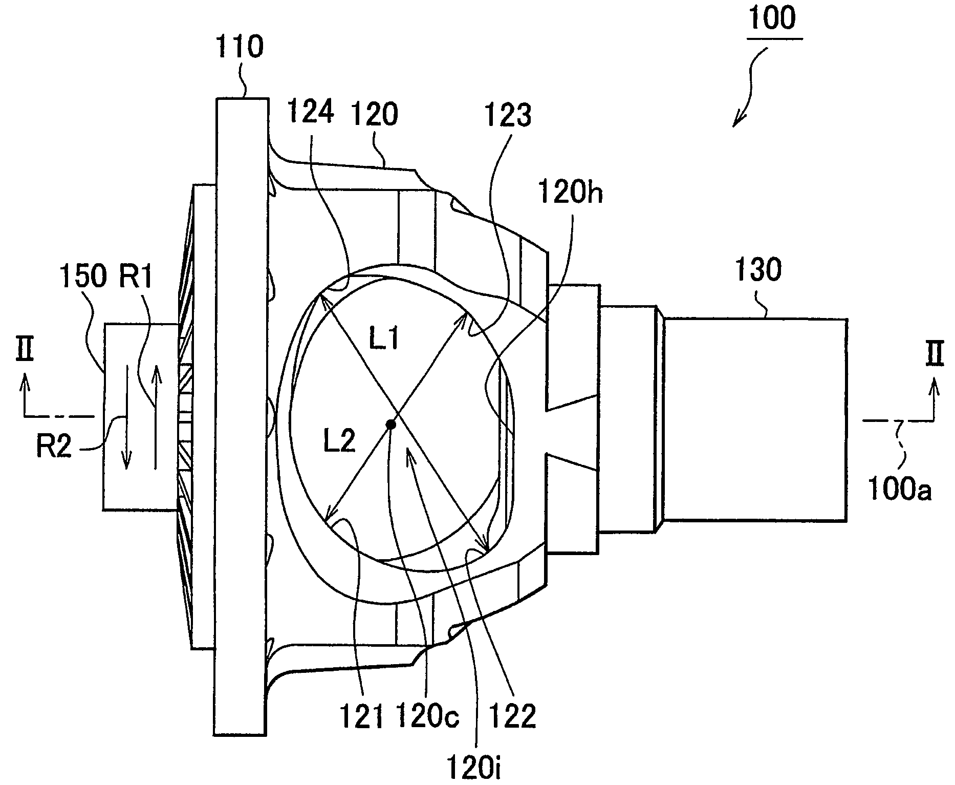
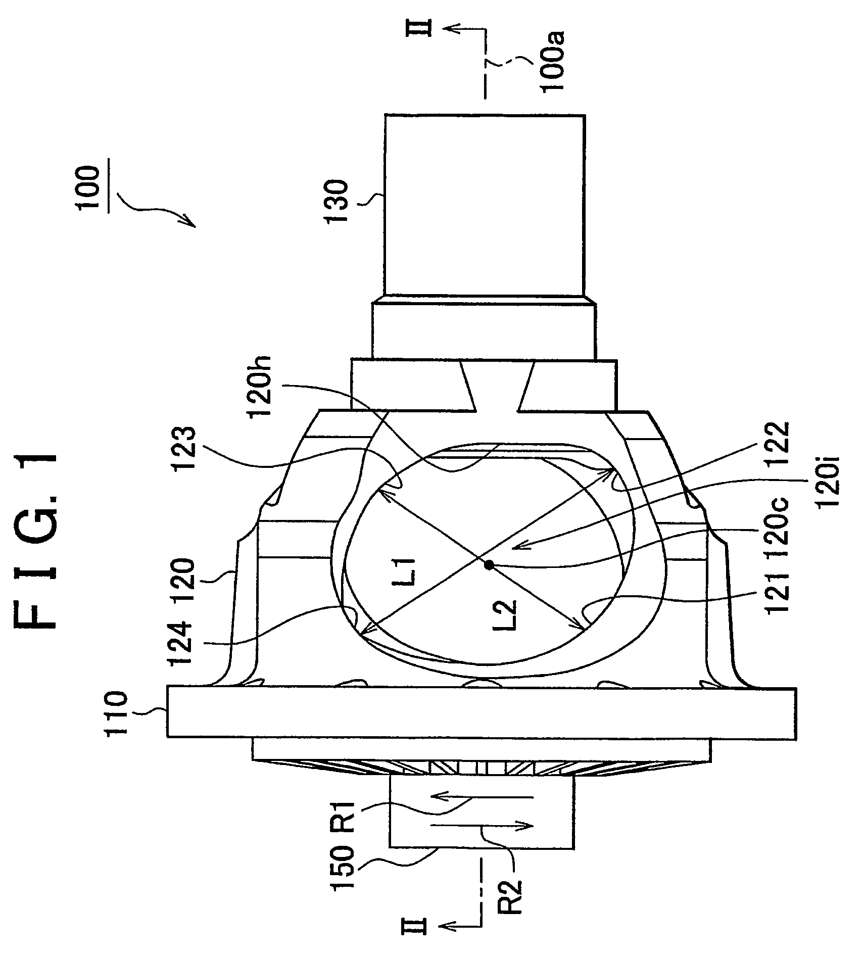
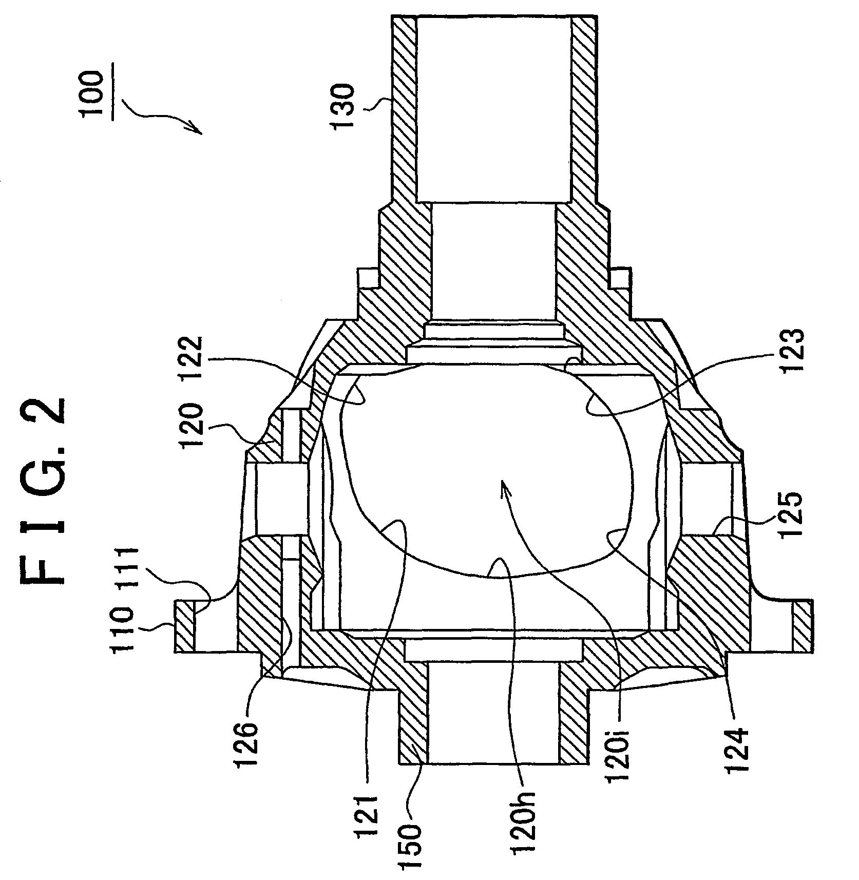
[0058]FIG. 11 is a cross sectional view of the differential gear unit according to the invention. Referring to FIG. 11, a pinion 143 which divides power; a pinion shaft 141 which supports the pinion 143; a pin 142 which positions the pinion shaft 141; and paired side gears 144 meshed with the pinion 143 are provided in the internal space 120i. Note that, in FIG. 11, a constant-velocity joint is not provided in the side gear 144. However, an element of the constant-velocity joint may be integrally provided in the side gear 144.

[0059]The side gear 144 is connected to the drive shaft, and an output from the side gear 144 is transmitted to a wheel. The output portion 130 is connected to the propeller shaft. Note that the differential gear unit 100 in the embodiment is used as a front differential for a four-wheel drive vehicle without a center differential.

[0060]The pinion shaft 141 is provided so as to penetrate the internal space 120i. The pinion 143 can be rotated about the pinion sh...

second embodiment

[0080]So far, the differential gear unit according to the first or second embodiment of the invention and the vehicle provided with the drive unit including the differential gear unit have been described. Meanwhile, the differential gear unit and the drive unit can be realized in various modified embodiments. First, the differential gear unit can be used not only as the differential gear unit for the front wheel and the rear wheel of an automobile but also as the center differential for a four-wheel drive vehicle or a six-wheel drive vehicle. Also, the differential gear unit can be applied not only to an automobile using a gasoline engine as a power source but also to a hybrid vehicle using gasoline and electric power as power, or a fuel cell vehicle.

[0081]So far, description has been made concerning the case where the invention is applied to a differential gear unit for a vehicle. However, a differential gear unit to which the invention is applied is not limited to a differential g...


PUM


Abstract

A differential gear unit divides an input driving force into first and second outputs, and permits a difference between the first and second outputs. The differential gear unit includes a differential case serving as a casing that defines an internal space and an opening communicated with the internal space and that is rotatable in a given direction and an opposite direction. The differential case includes a flange portion as an input portion to which the driving force is input. The differential case is configured such that the fatigue life of the differential case when the driving force is repeatedly input in the flange portion in the direction R1 is longer than the fatigue life of the differential case when the driving force is repeatedly input in the flange portion in the opposite direction; R1 is the rotational direction in which the vehicle runs forward.

Description

CROSS-REFERENCE TO RELATED APPLICATIONS[0001]The present application is based on Japanese Patent Application No. 2004-024091 filed on Jan. 30, 2004, the entire contents of which are hereby incorporated by reference herein.BACKGROUND OF THE INVENTION[0002]1. Field of the Invention[0003]The invention relates to a differential gear unit. More particularly, the invention relates to a differential gear unit used in an automobile.[0004]2. Description of the Related Art[0005]A conventional type of differential gear unit for an automobile is disclosed in, for example, Japanese Patent Laid-Open Publication No. 58-144141. The Japanese Patent Laid-Open Publication No. 58-144141 discloses a technology in which simplified pinion shafts for four-pinions, instead of a pinion shaft for two pinions, is provided in the differential gear unit which conventionally includes an undivided differential case and the pinion shaft for two pinions, that is supported with each end portion inserted in the differ...

Claims


Application Information

Patent Timeline
Patent Type & Authority Patents(United States)
IPC IPC(8): F16H48/08F16H57/02B60K17/16F16H48/38F16H48/40
CPCF16H48/08Y10T74/2188Y10T74/2186F16H48/40B60K17/16
Inventor KOHNO, TETSUYAYASUDA, YUJI
Owner TOYOTA JIDOSHA KK
Why Eureka
Try Eureka