Method of controlling operation of rock drilling rig, and rock drilling rig

a drilling rig and rock technology, applied in the direction of drilling machines and methods, chemistry apparatus and processes, borehole/well accessories, etc., can solve the problem of rapid danger of success in drilling

Inactive Publication Date: 2010-11-09
SANDVIK MINING & CONSTR OY
View PDF21 Cites 6 Cited by
  • Summary
  • Abstract
  • Description
  • Claims
  • Application Information

AI Technical Summary

Benefits of technology

[0007]The method according to the invention is characterized by determining the rate of flow of the flushing medium of the rock drilling rig on the basis of the rate of flow of the flushing medium flowing in a flushing channel system of the rock drilling rig, comparing the rate of flow of the flushing medium to a limit value set for the rate of flow of the flushing medium, and when the rate of flow of the flushing medium drops below said limit value, increasing pressure of the flushing medium.
[0010]By controlling the operation of the rock drilling rig by influencing the pressure of the flushing medium, the aim is to clear a clog being formed in a flushing channel system of the rock drilling rig without influencing the other sectors of drilling. When a clog is about to be formed in the flushing channel system, the rate of flow of the flushing medium in the flushing channel system decreases, but the aim is to clear the clog by increasing the pressure of the flushing medium and maintain the rate of flow of the flushing medium at least at a set value set therefor while at the same time normal drilling operation is maintained. Simultaneously, the functioning of the flushing is ensured and strain imposed on drilling equipment is reduced.

Problems solved by technology

If, during drilling, problems occur in the flushing, successful drilling quickly becomes endangered.

Method used


Image

  • Method of controlling operation of rock drilling rig, and rock drilling rig
  • Method of controlling operation of rock drilling rig, and rock drilling rig

Examples


Embodiment Construction

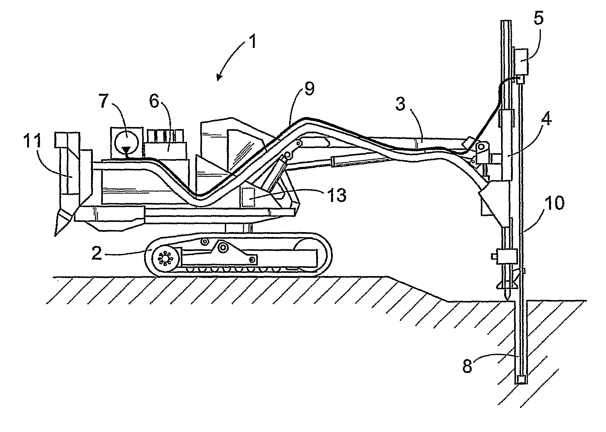
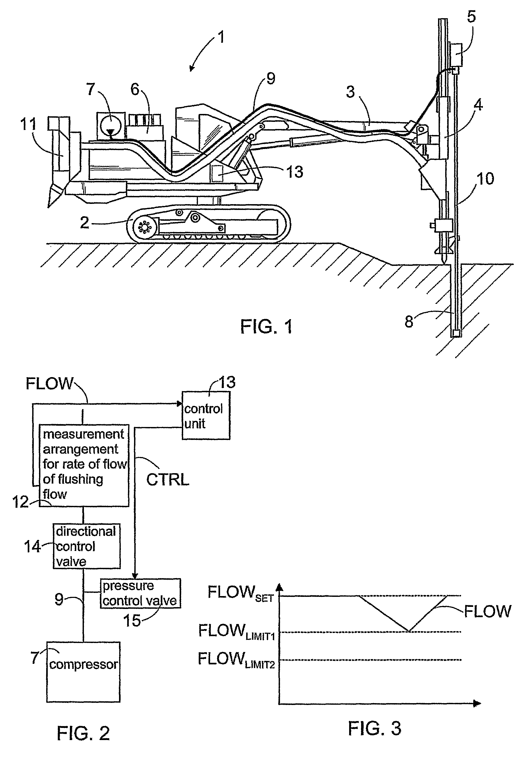
[0015]FIG. 1 schematically shows a structure of a rock drilling rig 1. The rock drilling rig 1 comprises a movable carrier 2 provided with a boom 3 whose free end is provided with a feed beam 4. Furthermore, the feed beam 4 is provided with a rock drill 5 which can be moved with respect to the feed beam 4. The rock drilling rig 1, including the devices connected thereto, are driven by power produced by a motor 6 arranged on the carrier 2, so that the rock drilling rig 1 is an independently moving and operating unit. Typically, the motor 6 is a combustion motor, e.g. a diesel motor. The rock drilling rig 1 according to FIG. 1 further comprises a compressor 7 driven by the motor 6 such that pressurized air generated by the compressor 7 is used for flushing a borehole 8 in order to remove drilling waste, i.e. drill cuttings, out of the borehole 8. In such a case, pressurized air, which is used as a flushing medium, is fed via a flushing channel system from the compressor 7 through a to...


PUM


Abstract

A method of controlling operation of a rock drilling rig, and a rock drilling rig. A rate of flow of a flushing medium of the rock drilling rig is determined, and the operation of the rock drilling rig is controlled on the basis of the determined rate of flow by influencing pressure of the flushing medium.

Description

CROSS REFERENCE TO RELATED APPLICATIONS[0001]This application is the National Stage of International Application No. PCT / FI2007 / 050199, filed Apr 18, 2007, and claims the benefit of Finnish Application No. 20065252, filed Apr 21, 2006.BACKGROUND OF THE INVENTION[0002]The invention relates to a method of controlling operation of a rock drilling rig, wherein a rate of flow of a flushing medium of the rock drilling rig is determined and the operation of the rock drilling rig is controlled on the basis of said rate of flow of the flushing medium.[0003]The invention further relates to a rock drilling rig comprising means for feeding a flushing medium into a borehole for removing drill cuttings being produced during drilling out of the borehole, a measurement arrangement for determining a rate of flow of the flushing medium to be fed into the borehole, and at least one control unit for controlling operation of the rock drilling rig on the basis of the rate of flow of the flushing medium t...

Claims


Application Information

Patent Timeline
Patent Type & Authority Patents(United States)
IPC IPC(8): E21B21/08E21B44/00
CPCE21B21/08E21B44/02
Inventor SORMUNEN, TAPANISALONEN, MARKUSVIRTANEN, ISTO
Owner SANDVIK MINING & CONSTR OY
Why Eureka
Try Eureka