Unlock instant, AI-driven research and patent intelligence for your innovation.

Abnormality diagnosis apparatus for internal combustion engine

a technology for internal combustion engines and diagnostic equipment, which is applied in the direction of electric control, instruments, braking systems, etc., can solve the problems of bad fuel, fuel that is not usable for gasoline engines,

Inactive Publication Date: 2010-11-16
DENSO CORP
View PDF6 Cites 10 Cited by
  • Summary
  • Abstract
  • Description
  • Claims
  • Application Information

AI Technical Summary

Benefits of technology

Accurately determines fuel system abnormalities by preventing misdiagnosis caused by other fuel contamination, ensuring that normal states are not incorrectly identified as abnormal and allowing for early detection of contamination.

Problems solved by technology

Therefore, the driver may supply light oil to a vehicle having the gasoline engine by mistake.
In the above case, the light oil is other fuel that is not usable for the gasoline engine.
Also, bad fuel, which is intentionally made by mixing other fuel into gasoline, may be supplied to the vehicle.
Accordingly, there is a possibility of misdiagnosis for erroneously determining that there is the abnormality in the fuel system disadvantageously.

Method used


Image

  • Abnormality diagnosis apparatus for internal combustion engine
  • Abnormality diagnosis apparatus for internal combustion engine
  • Abnormality diagnosis apparatus for internal combustion engine

Examples


first embodiment

[0019]The first embodiment of the present invention will be described with reference to FIGS. 1 to 6. Referring to FIG. 1, a general configuration of an engine control system is described.

[0020]An engine 11 is an internal combustion engine and is connected with an intake pipe 12. An air cleaner 13 is provided most upstream of the intake pipe 12, and an air flow meter 14 is provided to the intake pipe 12 downstream of the air cleaner 13 for detecting an intake air amount. A throttle valve 16, an opening of which is adjusted by a motor 15, is provided to the intake pipe 12 downstream of the air flow meter 14. Also, a throttle opening sensor 17 is provided to the intake pipe 12 downstream of the air flow meter 14 for detecting a throttle opening of the throttle valve 16.

[0021]Further, a surge tank 18 is provided to the intake pipe 12 downstream of the throttle valve 16, and the surge tank 18 is connected with an intake manifold 20 that introduces air to each cylinder of the engine 11. ...

second embodiment

[0057]Next, with reference to FIG. 7, the second embodiment of the present invention will be described.

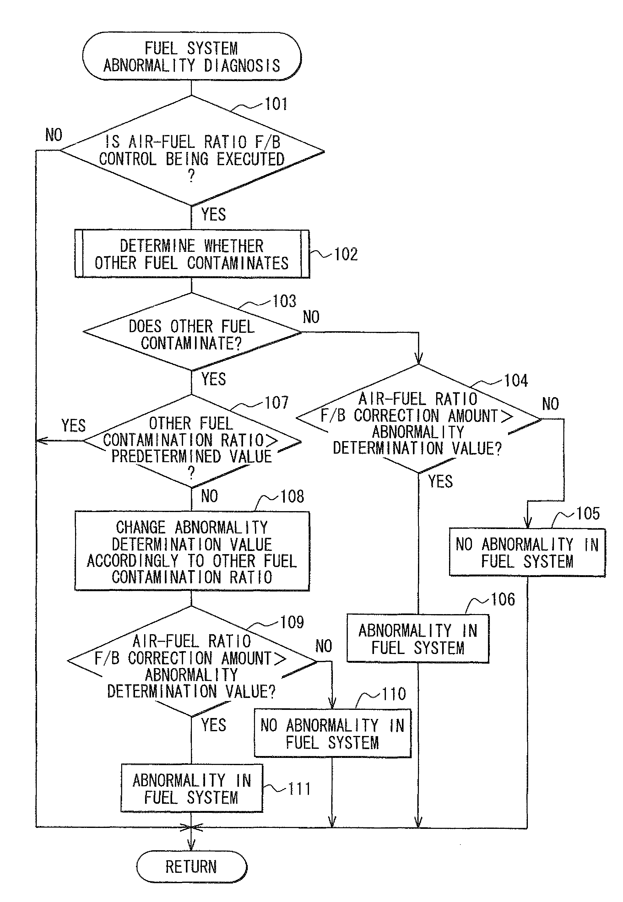
[0058]In the first embodiment, when it is determined that the other fuel contaminates the supply fuel, the abnormality determination value for the fuel system is changed in accordance with the contamination ratio of the other fuel, and further, when the contamination ratio of the other fuel becomes larger than the predetermined value, the abnormality diagnosis in the fuel system is prohibited. However, by executing a fuel system abnormality diagnosis routine shown in FIG. 7, when it is determined that the other fuel contaminates the supply fuel, the abnormality diagnosis in the fuel system is prohibited such that the misdiagnosis of erroneously determining that there is the abnormality in the fuel system, which misdiagnosis is caused by the contamination of the other fuel, is prevented.

[0059]In the fuel system abnormality diagnosis routine shown in FIG. 7, when it is determined at ...


PUM


Abstract

An abnormality diagnosis apparatus for an internal combustion engine includes an abnormality diagnosis unit, an other fuel contamination determination unit, and a misdiagnosis prohibition unit. The abnormality diagnosis unit determines whether there is an abnormality in a fuel system based on an output from an exhaust gas sensor mounted on an exhaust duct of the internal combustion engine. The other fuel contamination determination unit determines whether an other fuel contaminates a supply fuel supplied to the internal combustion engine. The misdiagnosis prohibition unit conducts one of (a) changing an abnormality determination condition for the abnormality diagnosis in the fuel system and (b) prohibiting the abnormality diagnosis in the fuel system, when the other fuel contamination determination unit determines that the other fuel contaminates the supply fuel.

Description

CROSS REFERENCE TO RELATED APPLICATION[0001]This application is based on and incorporates herein by reference Japanese Patent Application No. 2007-215401 filed on Aug. 22, 2007.BACKGROUND OF THE INVENTION[0002]1. Field of the Invention[0003]The present invention relates to an abnormality diagnosis apparatus for an internal combustion engine, which apparatus determines whether there is an abnormality in a fuel system based on an output from an exhaust gas sensor mounted on an exhaust duct of the internal combustion engine.[0004]2. Description of Related Art[0005]For example, JP-A-2001-329894 (for example, P. 2) describes an air-fuel ratio control system that performs a abnormality diagnosis of a fuel system (for example, fuel injection valve, fuel pump) for an internal combustion engine. The air-fuel ratio control system establishes an air-fuel ratio feed-back correction amount for a feed-back control based on an output from an exhaust gas sensor (air-fuel ratio sensor, oxygen sensor...

Claims


Application Information

Patent Timeline
Patent Type & Authority Patents(United States)
IPC IPC(8): G01M15/10
CPCF02D35/027F02D41/1495F02D41/222F02P5/1527F02D41/0025Y02T10/36F02D2041/228Y02T10/46F02D41/2461Y02T10/30Y02T10/40
Inventor TANAKA, TOSHIHIKO
Owner DENSO CORP