Dispenser for rolls

a dispenser and roll technology, applied in the field of dispensers, can solve the problems of paper waste unnecessarily, difficulty in determining when a roll is substantially exhausted, and affect the function and reliability of the dispenser, and achieve the effect of reducing the speed of the second roll

Inactive Publication Date: 2010-11-16
ESSITY HYGIENE & HEALTH AB
View PDF19 Cites 26 Cited by
  • Summary
  • Abstract
  • Description
  • Claims
  • Application Information

AI Technical Summary

Benefits of technology

[0014]allowing the second roll to move from the reserve position into the dispensing position.
[0019]The invention also relates to a dispenser for carrying out the above method. The dispenser contains one or more rolls of flexible sheet material, each of said rolls having spindle means extending axially outwardly beyond the ends thereof, wherein a first roll is located in a dispensing position and a second roll is located in a reserve position above said dispensing position. The rolls may preferably, but not necessarily, be placed in the dispenser with their axes at substantially right angles to a rear surface of a wall mounted dispenser. This roll arrangement also allows relatively large diameter rolls to be placed in a dispenser while extending a relatively small distance from the wall. The reason for this is that while roll sizes will increase with increasing diameters, the width of the rolls remains substantially the same for the same type of web to be dispensed.
[0023]According to one embodiment, the at least one first sensor means is mounted on a pivot joint substantially parallel to an end surface of the first roll. The said first sensor means may be provided with a guide slot allowing the spindle means extending out of the end surfaces of the roll to pass the first sensor means This arrangement allows a roll to move from the reserve position and at least partially past the first sensor means into contact with the first catch in the dispensing position.
[0027]The first sensor means may comprise a single sensor on either side of the roll or one sensor on both sides. When a first sensor is located in an active position against the end surface of the first roll, the biasing force on said first sensor may also allow it to act as a brake on the first roll to prevent excessive amounts of web to be dispensed.
[0031]In this way paper is always available on the first roll during the roll change. The relatively small first roll needs to be moved away from the regular dispensing position to leave space for the new second roll, allowing it to drop into position. The first roll may be moved to its stub roll position by gravity, by pull force from paper that is removed by a user, or by a combination of both. To ensure that the first roll is correctly located in the stub roll position, the second roll may push the first roll into the stub roll position just before reaching its dispensing position. When this occurs, sufficient inertia may be transferred to the stub roll to push it into the sub roll position. At the same time, the speed of the second roll is reduced, resulting in a relatively soft landing of the new roll in the dispensing position.

Problems solved by technology

Although a large number of alternative prior art solutions are available, their function and reliability may be affected by a number of inherent problems typical for this type of dispenser.
One problem with this solution is the difficulty of determining when a roll is substantially exhausted.
If the roll is removed before it is exhausted, paper is wasted unnecessarily.
The latter case may lead to a further problem, wherein a roll that becomes exhausted before it has moved to its second position may remain in or near the dispensing position.
A further problem relates to the friction between the roll support in the dispenser and the spindles or adaptors supporting the roll.
The basic problem for dispensers of this type in general is that the automatic roll change is dependent on several different things occurring more or less at the same time.
In many cases something goes wrong here and the automatic roll change is interrupted.

Method used


Image

  • Dispenser for rolls
  • Dispenser for rolls
  • Dispenser for rolls

Examples


Embodiment Construction

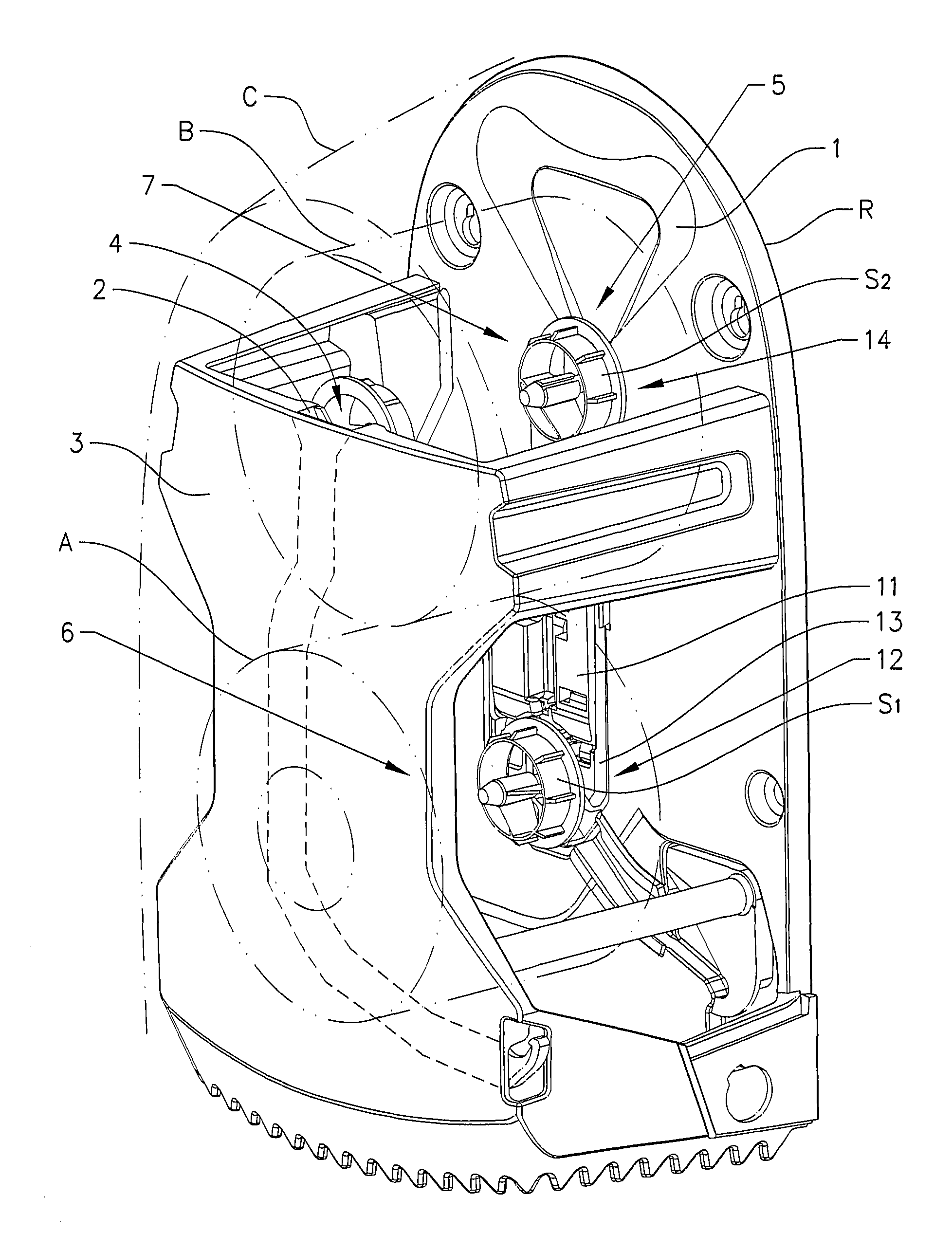
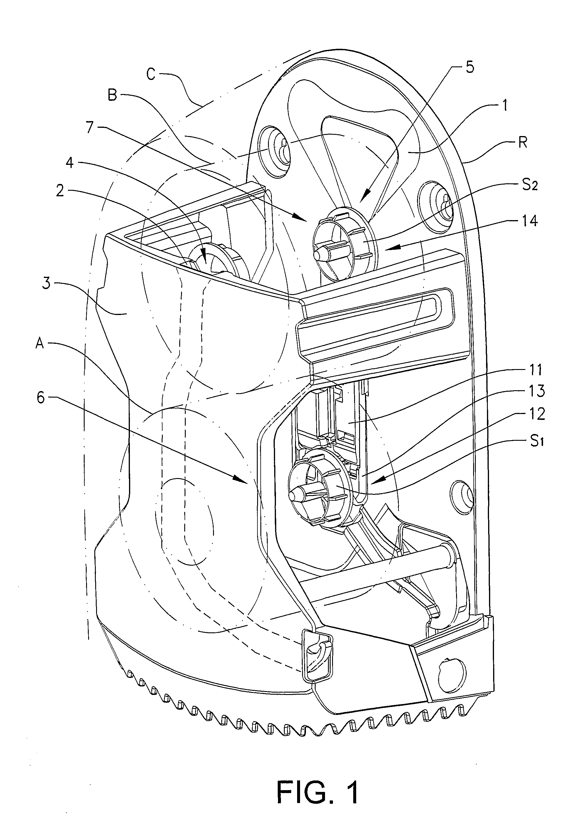
[0040]FIG. 1 show a schematic chassis for a wall mounted dispenser according to the invention. In the figure, an outer cover C surrounding the front and sides of the dispenser has been removed for clarity and is indicated with dash-dotted lines only. In the subsequent text the terms “inner” and “outer” are used to denote the position of components in relation to a rear section R, unless otherwise indicated. The rear section R is intended to be mounted on a wall or a similar vertical or near vertical surface. In the examples described below, the rolls are placed in the dispenser with their axes at substantially right angles to the rear section R of the wall mounted dispenser. The dispenser in this particular example can be used with any suitable type of coreless rolls, rolls with cores and solid rolls, as described above. However, the example below only describes rolls with cores having central spindle means S1, S2 inserted into the ends of the roll and extending axially outwardly be...


PUM


Abstract

A dispenser for rolls of web-shaped material, includes a housing having at its bottom part an outlet opening for the web-shaped material and a space for at least two rolls arranged substantially horizontally. A first part of the space is located adjacent the outlet opening and is intended for a first roll in a dispensing position and a second part of the space includes a locking element intended to keep the second roll in standby position. The first part is provided with holding elements for keeping the first roll in use position, the holding elements are spring-loaded and cooperate with the locking elements such that when a roll is located in the first space the locking element prevent the standby roll from falling down, but when the first roll is released from the first space the locking element release and permits the standby roll to occupy the dispensing position.

Description

TECHNICAL FIELD[0001]The present invention relates to a dispenser for rolls of web-shaped material, such as paper and non-woven sheets, said dispenser comprising a housing having at its bottom part an outlet opening for the web-shaped material and a space for at least two rolls. A first part of the space is located adjacent the outlet opening and is intended for a first roll in a dispensing, or use position and a second part of the space comprises a locking means intended to keep the second roll in standby position. The first part is provided with holding means for keeping the first roll in use position, said holding means is spring-loaded and cooperates with the locking means in such a way that when a roll is located in place in the first space the locking means prevents the standby roll from falling down, but when the first roll is released from the first space the locking means will be released and permit the standby roll to fall down to the dispensing position in the first space...

Claims


Application Information

Patent Timeline
Patent Type & Authority Patents(United States)
IPC IPC(8): B65H19/00
CPCA47K10/38A47K2010/3854A47K2010/3253
Inventor HJORT, ERIKPOMMER, STIGMOLLER, PER
Owner ESSITY HYGIENE & HEALTH AB
Why Eureka
Try Eureka