Telescoping wing locking system

Inactive Publication Date: 2010-11-16
MUNDUS GROUP
View PDF4 Cites 14 Cited by
  • Summary
  • Abstract
  • Description
  • Claims
  • Application Information

AI Technical Summary

Benefits of technology

[0006]Embodiments of the present telescoping wing locking system allow for rigid extension of telescopic wing segments while allowing for smooth retraction with less concern of wing segments becoming undesirably stuck together. Embodiments also allow for the locking of wing segments of

Problems solved by technology

While this achieves the goal of rigidity, there is a tendency for segments to stick or jam together so that the systems are prone to retraction failure.
This creates operational hazards when not accomplished smoothly.
In addition

Method used


Image

  • Telescoping wing locking system
  • Telescoping wing locking system

Examples


Example

[0014]While the invention is susceptible of various modifications and alternative constructions, certain illustrated embodiments thereof have been shown in the drawings and will be described below in detail. It should be understood, however, that there is no intention to limit the invention to the specific form disclosed, but, on the contrary, the invention is to cover all modifications, alternative constructions, and equivalents falling within the spirit and scope of the invention as defined in the claims.

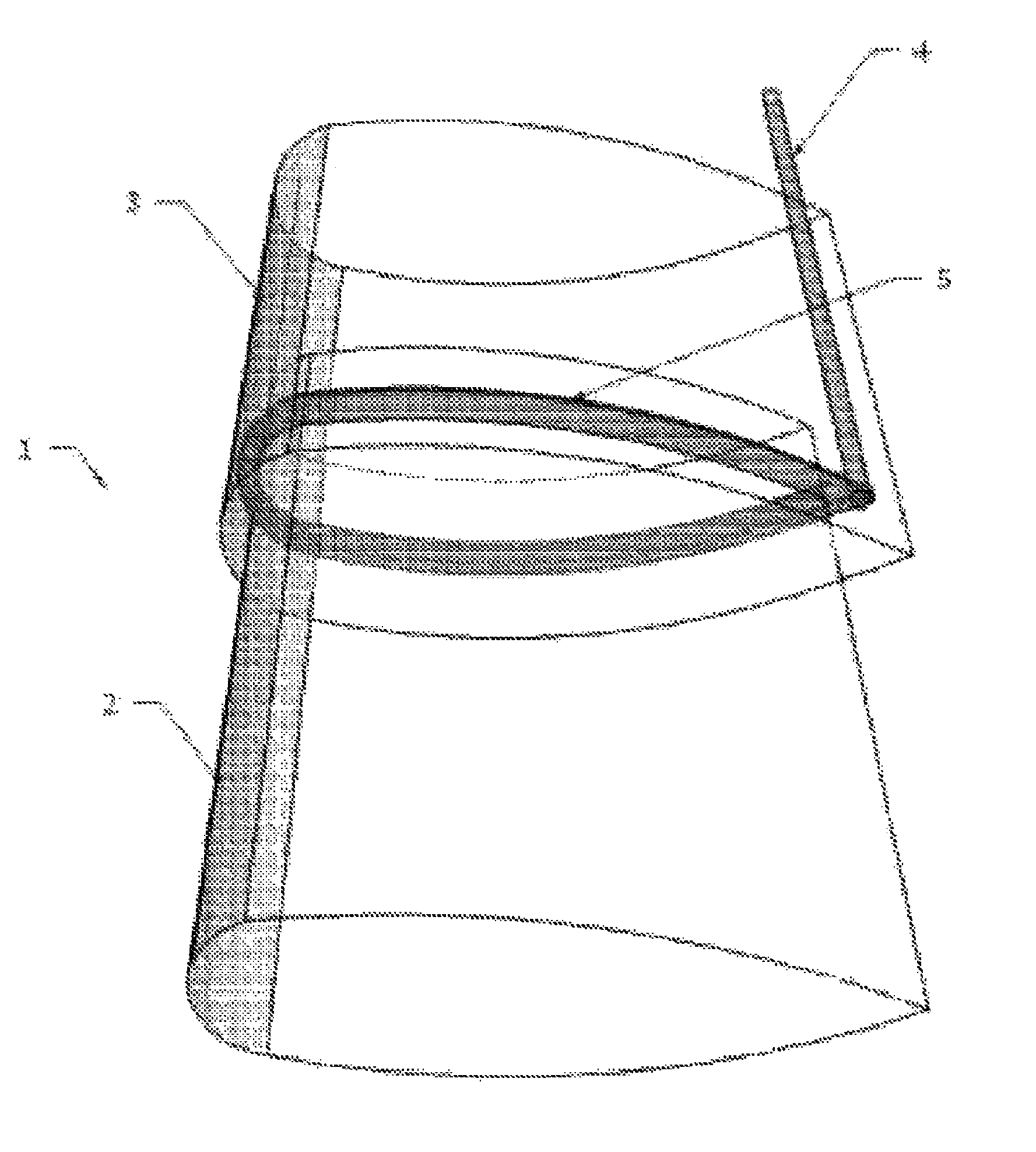
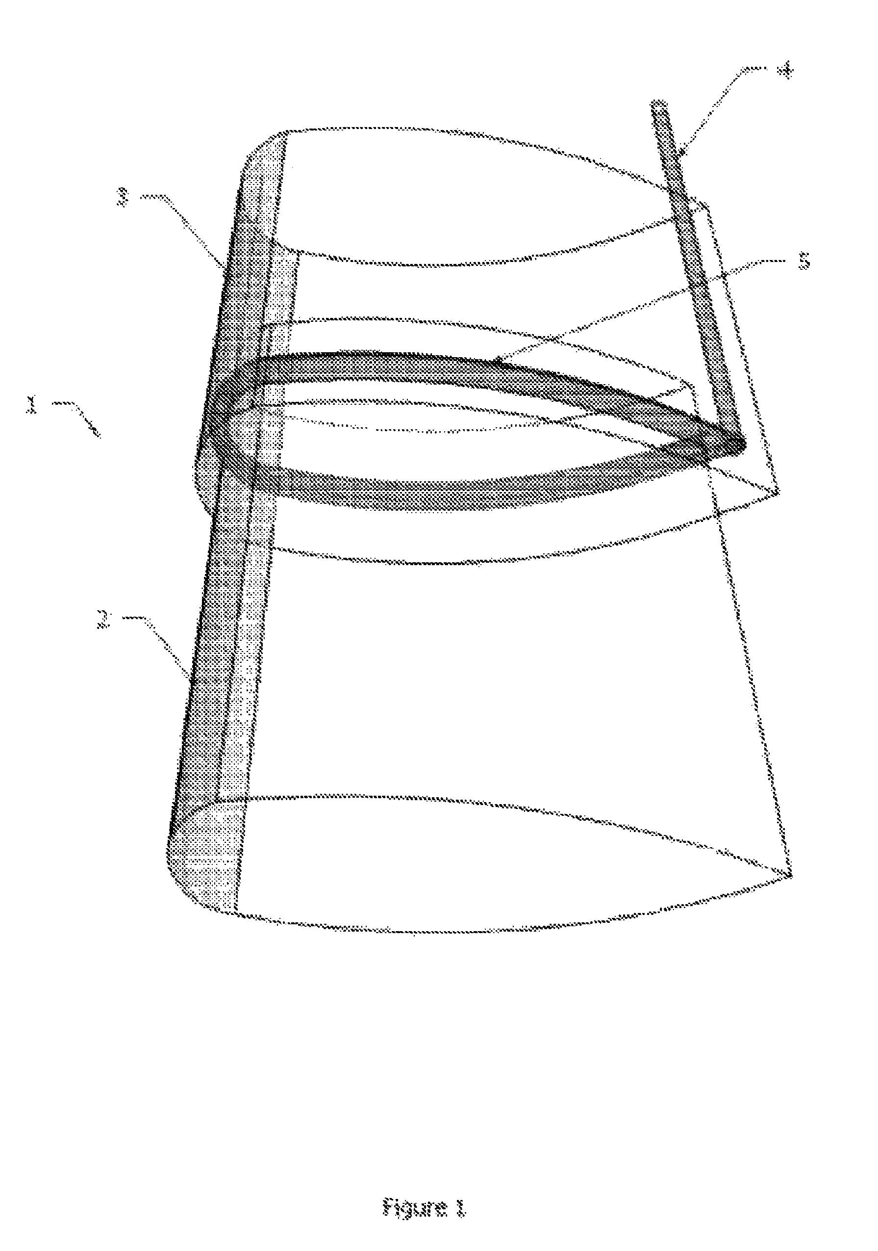
[0015]As shown in the FIGURE for purpose of illustration, the telescoping wing locking system is embodied in a system that allows for multiple locking positions while maintaining rigidity of the wings, reduces the risk of retraction failure, reduces the wear and tear of wing segments, and allows for the use of simpler wing segment shapes.

[0016]In the following description, the use of “or” indicates a non-exclusive alternative without limitation unless otherwise noted. The use of “...


PUM


Abstract

Disclosed is a telescoping wing locking system for use in aircraft having wings that collapse and expand in a telescoping fashion, such as aircraft designed for use on roadways. Companion wing segments are locked in place when gas is supplied to inflate a bladder located between overlapping sections of the wing segments. Wing segments are unlocked when gas is removed from the bladder so that it deflates and allows the wing segments to be moved relative to each other. The wing segments may be locked in any position relative to each other in which a section of one segment overlaps a section of the neighboring segment with the bladder between.

Description

FIELD OF THE INVENTION[0001]The invention relates to generally to a system for controlling telescopic aircraft wing operation, and more particularly to a system for the locking of collapsible wing segments.BACKGROUND OF THE INVENTION[0002]To those familiar with the developing art of designing and constructing road-to-air crafts, the necessity for a collapsible wing system is obvious. One design for such collapsible wing system is the use of a telescoping aircraft wing in which a number of wing segments are used with more outboard segments being smaller than adjacent inboard wing segments such that the more outboard segments may be collapsed in a telescope fashion within a more inboard, neighboring, larger wing section.[0003]Such a telescoping wing design is described in U.S. Pat. No. 4,824,053 to Branko Sarh. The '053 wing makes use of conventional metal rib forms where a metal skin is attached. Longitudinal spar segments associated with wing segments are tubular in shape and reduce...

Claims


Application Information

Patent Timeline
IPC IPC(8): B64C3/54
CPCB64C3/54
Inventor LEVINE, BARTFIELD, KEITH MICHAEL
Owner MUNDUS GROUP
Why Eureka
Try Eureka