
Combine harvester clean crop elevator

a technology of combine harvester and elevator, which is applied in the direction of digger harvester, agriculture tools and machines, solid separation, etc., can solve the problems of crop material jamming, inability to increase the conveying performance of the conveyor device, etc., to reduce the installation space required inside the combine harvester for the conveyor device, the diameter of the conveyor auger may be reduced, and the conveying performance increased

Inactive Publication Date: 2010-11-16
CLAAS SELBSTFAHRENDE ERNTEMASCHINEN GMBH
View PDF16 Cites 19 Cited by
  • Summary
  • Abstract
  • Description
  • Claims
  • Application Information

AI Technical Summary

Benefits of technology

[0007]Accordingly, it is an object of the present invention to provide a combine harvester which avoids the disadvantages of the prior art.
[0008]More particularly, it is an object of the present invention to provide a combine harvester in which the conveying performance of the conveyer device is increased.

Problems solved by technology

Since, however, the quantity of crop material to be conveyed is essentially not limited by the distribution of the crop material onto the conveyor plates of the elevator, but rather is limited by the cross section in the side panel of the combine harvester in the region of the intake region of the elevator, it is not possible to increase the conveying performance of the conveyor device using a design as described in U.S. Pat. No. 6,350,197 B1.
A further disadvantage of the combine harvester known from U.S. Pat. No. 6,350,197 B1 is that, due to the conical design of the transfer element, crop material becomes jammed, in particular when it is moist, since it is not possible to actively convey the crop material into the elevator, and, instead, it is merely pressed into the elevator by crop material that arrives subsequently.

Method used


Image

  • Combine harvester clean crop elevator
  • Combine harvester clean crop elevator
  • Combine harvester clean crop elevator

Examples


Embodiment Construction

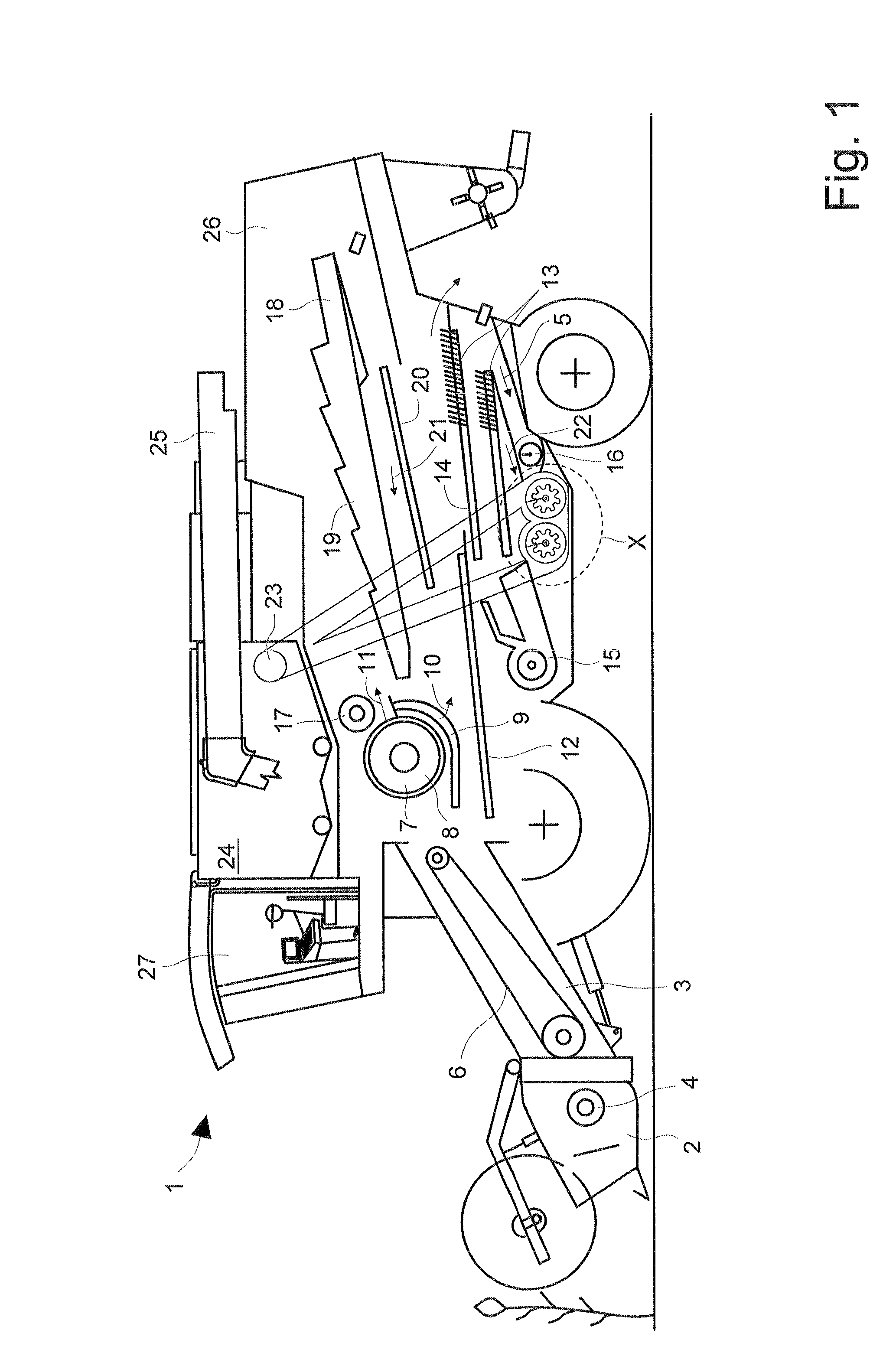
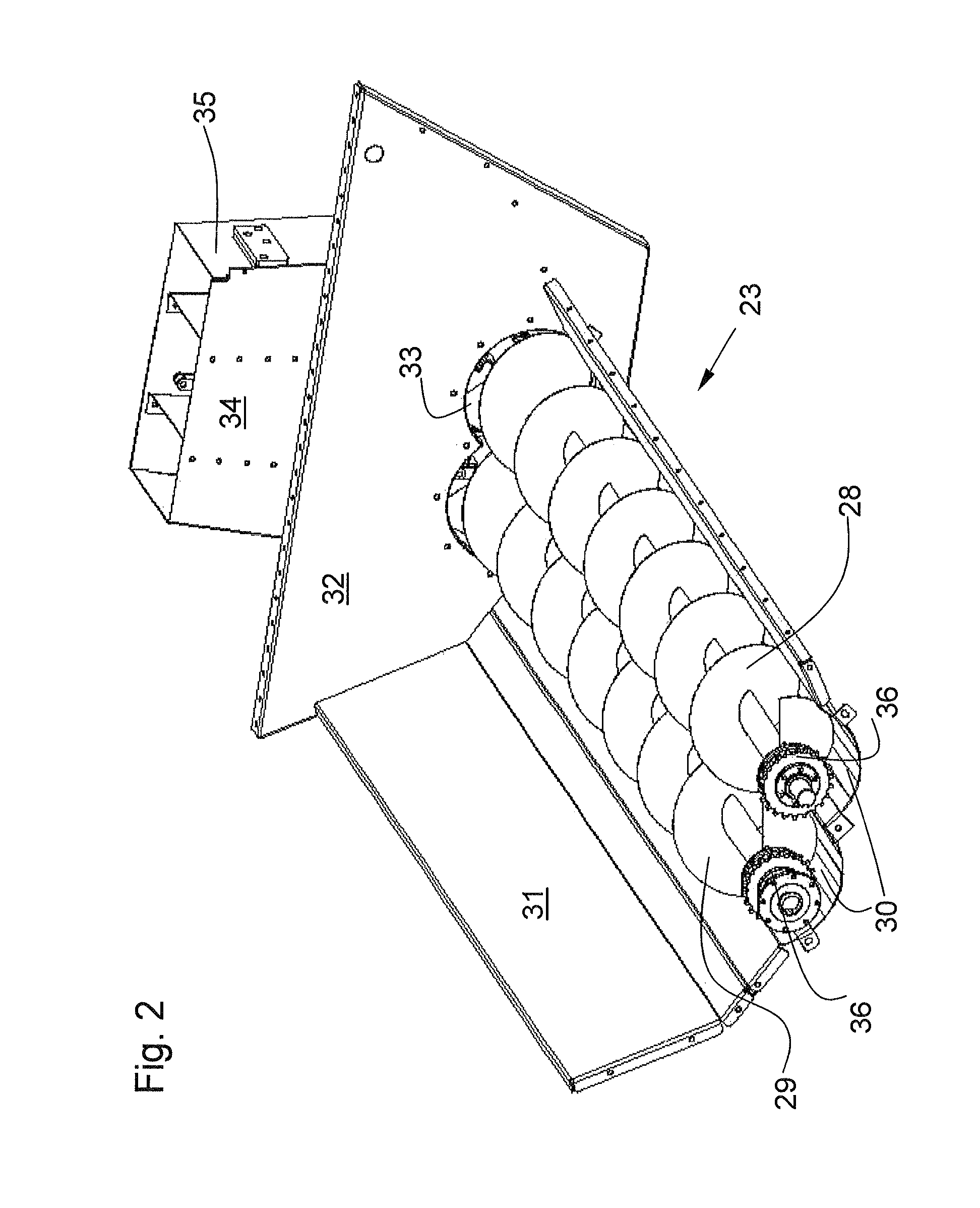
[0029]Combine harvester 1 shown schematically in FIG. 1 is composed of a support frame which is connected to the ground drive, and on which a multiple-component machine housing 26 is mounted. To protect the driver of combine harvester 1 from disturbing environmental influences, a closed driver's cab 27 is located in the front region. Combine harvester 1 includes a grain-cutting device 2 which is connected in a manner known per se to feed rake 3 of combine harvester 1. Cross auger component 4 of header 2 transfers the crop material to feed rake 3 which transfers the crop material via circulating conveyor 6 in its upper, rear region to threshing mechanism 7 of combine harvester 1. In threshing mechanism 7, which may be designed to include one cylinder or several cylinders, the crop material is conveyed between cylinders 8 and a concave 9 which at least partially encloses cylinders 8, thereby separating it into at least two sub-streams 10, 11. First sub-stream 10 is composed essentiall...


PUM


Abstract

A combine harvester has at least one cleaning device which includes at least one sieve and one cleaning fan, at least one conveyor device for conveying at least a portion of the crop material that exits the cleaning device into a higher region of the combine harvester and including at least one elevator having a lower intake region and an upper transfer region, the crop material being conveyed in the elevator via conveyor plates which are situated on a circulating chain, and the elevator includes, in its lower region, at least two interspaced deflection axles for the circulating chain, which are oriented transversely to the longitudinal extension of the combine harvester.

Description

CROSS-REFERENCE TO RELATED APPLICATION[0001]The invention described and claimed hereinbelow is also described in German Patent Application DE 10 2008 014 001.5 filed on Mar. 13, 2008. This German Patent Application, whose subject matter is incorporated here by reference, provides the basis for a claim of priority of invention under 35 U.S.C. 119(a)-(d).BACKGROUND OF THE INVENTION[0002]The present invention relates to a combine harvester.[0003]Publication U.S. Pat. No. 6,350,197 B1 makes known a combine harvester for harvesting agricultural crop material such as grain, corn, beans, or even grass seed, in which the crop material that has been harvested using a header is separated into different material flows using a plurality of working units located inside the combine harvester. A cleaning device is located in a region of the combine harvester that is close to the ground; the cleaning device further subdivides the grains and admixtures such as chaff or ear components which were sepa...

Claims


Application Information

Patent Timeline
Patent Type & Authority Patents(United States)
IPC IPC(8): A01F12/60
CPCA01D41/12A01D61/02A01F12/46
Inventor HOLTMANN, BERNDTEROERDE, STEFANWESSELMANN, WINFRIEDBOENIG, INGOVIEREGGE, CHRISTOPHERBRUEGGEMANN, DANIELKORTE, HUBERTCLAES, ULRICHSCHULZ, WALDEMAR
Owner CLAAS SELBSTFAHRENDE ERNTEMASCHINEN GMBH
Learn More