Electronically steered, dual-polarized, dual-plane, monopulse antenna feed

a monopulse, antenna feed technology, applied in the direction of polarised antenna unit combinations, instruments, antennas, etc., can solve the problems of mechanical steering solution may have limitations, usually extremely short duration, minimal effect on pulse detection capabilities, etc., and achieve the effect of reducing the cost and weight of radar systems

Inactive Publication Date: 2010-11-16
LOCKHEED MARTIN CORP
View PDF5 Cites 23 Cited by
  • Summary
  • Abstract
  • Description
  • Claims
  • Application Information

AI Technical Summary

Benefits of technology

[0014]Further, the present invention relates to a device for electronically steering a RADAR beam in a monopulse RADAR system. Such a device may comprise a commutative RF switching network that sequentially activates and deactivates polarized feed horn pairs within a feed horn array so that the origination point of a monopulse RADAR beam generated by the array moves across at least one plane of the face of said array, thereby changing the field of view of the RADAR system.
[0017]Embodiments of such electronically-steered monopulse RADAR systems may be used in conjunction with a range of reflectors, including Cassegrain reflectors. A Cassegrain configuration may provide the same focal length as a prime focus reflector with a smaller size assembly, allowing such a system to be used in space-constrained settings. Because the present invention does not require mechanical actuators to accomplish beam steering, it may also enable reductions in the cost and weight of RADAR systems constructed according to the present invention.
[0018]Embodiments of such electronically-steered monopulse RADAR systems may also allow for beam steering in more than one planar direction by increasing the number of feed horn antennas in the feed horn array, or by changing the feed horn array configuration, and modifying the associated switching network accordingly.

Problems solved by technology

Changes in signal strength during a pulse are possible, but they are usually extremely short in duration and have a minimal effect on pulse detection capabilities.
Specifically with respect to RADAR-guided munitions, a mechanical steering solution may have some limitations.
There are a number of moving parts that, given the high-impact operating environment most munitions occupy, may be susceptible to failure and malfunction due to mechanical stresses.
Also, the number of overall components leads to increases in both cost and weight.

Method used


Image

  • Electronically steered, dual-polarized, dual-plane, monopulse antenna feed
  • Electronically steered, dual-polarized, dual-plane, monopulse antenna feed
  • Electronically steered, dual-polarized, dual-plane, monopulse antenna feed

Examples


Embodiment Construction

[0033]The following detailed description of the invention refers to the accompanying drawings. The same reference numbers in different drawings identify the same or similar elements. In addition, the following detailed description does not limit the invention. Instead, the scope of the invention is defined by the appended claims and equivalents thereof.

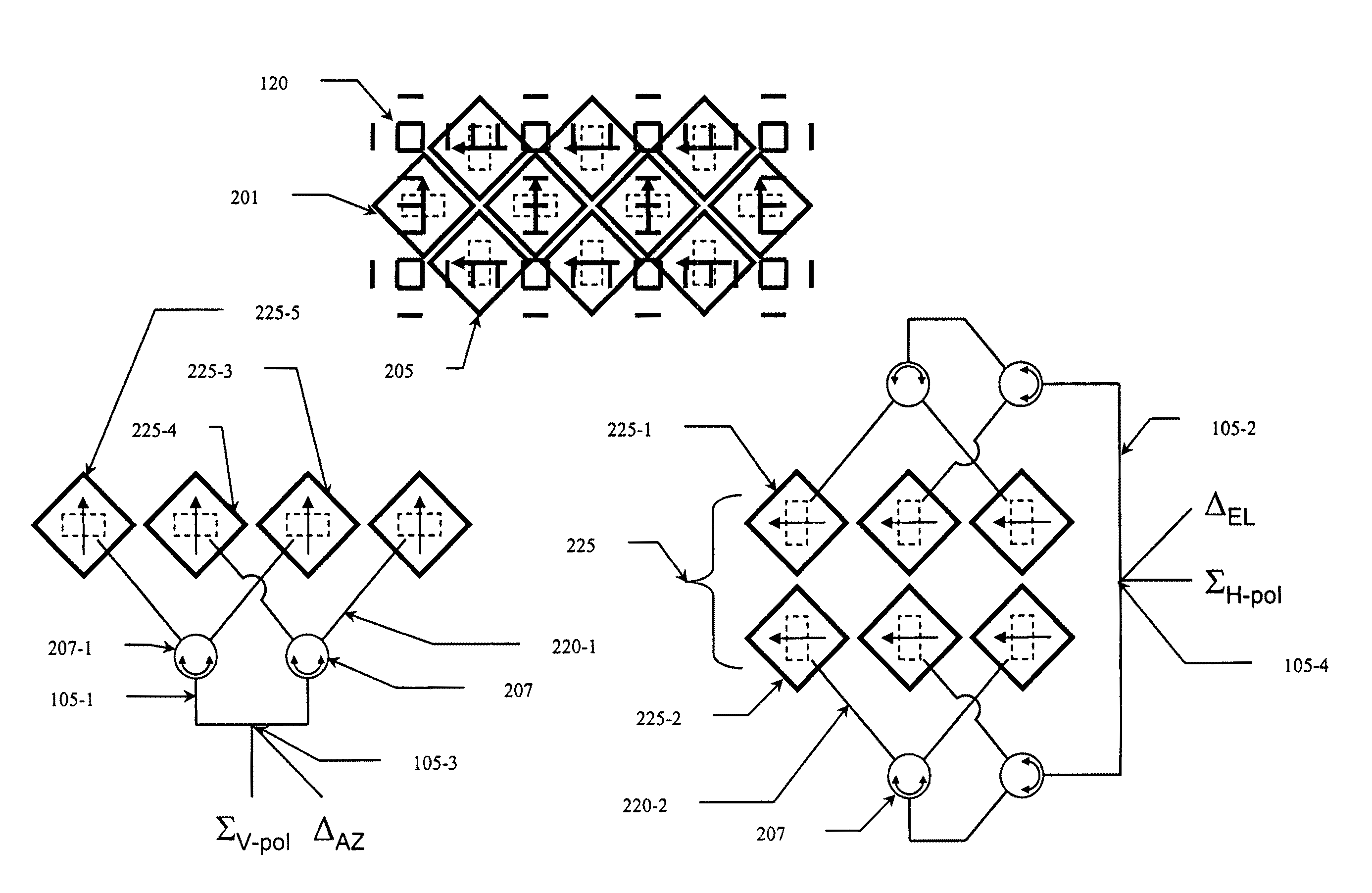
[0034]The present invention seeks to address the problems of cost, weight, and mechanical failure in RADAR tracking systems through the use of an electronically-steered monopulse RADAR system. It implements a dual-polarized, dual-plane monopulse, switched beam approach with a minimum number of switches and four-port RF devices. The system is based on a beam generated by a set of dielectrically-loaded diagonal feed horns having two orthogonal polarizations (e.g., vertically polarized horns and horizontally polarized horns) and an array of wires to control the beamwidth for each horn pair, enabling the creation of monopulse beams of con...


PUM


Abstract

A method and apparatus for electronically steering a RADAR beam across an array of feed horns by moving the phase center of the beam to different origination points on the array—each origination point being the phase center of a feed horn pair. Variations include polarized beams, polarized feed horns, dual-beam systems, dual direction steering, diagonal steering, and cross-polarized wire grids to control beamwidth.

Description

BACKGROUND[0001]1. Field of the Invention[0002]The present invention relates generally to RADAR systems and more particularly to the control and steering of RADAR beams and to the arrangement and structure of monopulse feed horn antenna arrays.[0003]2. Description of Related Art[0004]RADAR tracking systems are a fixture in most military arsenals, airports, and weather stations. They may be used to detect incoming projectiles, track aircraft trajectories, and / or locate and track targets of interest.[0005]RADAR systems include transmitter, receiver, and processing portions. RADAR systems also contain one or more antennas, depending on the RADAR type and the intended application, and the antennas are often mechanically steered to detect targets in a certain field of view. Space is a concern in modern RADAR applications, requiring smaller and more efficient RADAR systems. Cost may also be a factor, especially in single-use applications such as RADAR-guided munitions.[0006]Monopulse RADA...

Claims


Application Information

Patent Timeline
Patent Type & Authority Patents(United States)
IPC IPC(8): G01S13/00
CPCH01Q19/19H01Q21/24H01Q25/02
Inventor WEINSTEIN, MICHAEL E.
Owner LOCKHEED MARTIN CORP
Why Eureka
Try Eureka