Pneumatic tire with rib having widthwise sipes and circumferential sipe

a pneumatic tire and rib technology, applied in the field of pneumatic tires, can solve the problems of uneven wear of pneumatic tires having rib patterns, the demand for tire performance improvement from the market has never stopped, and the need for further improvement of uneven wear of pneumatic tires with rib patterns, etc., to achieve the effect of suppressing local increase of ground contact pressure in the ends of the ribs, reducing the compression amount of the ends of the rib in the circumferential direction and widthwise direction

Active Publication Date: 2010-11-23
THE YOKOHAMA RUBBER CO LTD
View PDF12 Cites 25 Cited by
  • Summary
  • Abstract
  • Description
  • Claims
  • Application Information

AI Technical Summary

Benefits of technology

[0005]An object of the present invention is to provide a pneumatic tire including a tread surface having a rib defined between circumferential grooves extending in the circumferential direction of the tire, in which uneven wear resistance of the rib can be improved and wet performance can be enhanced.
[0007]According to the present invention described above, the circumferential sipe and the widthwise sipes mentioned above enable shear strain in the widthwise direction of the rib acting on the ends of the rib facing the circumferential grooves when the tire is engaged with a ground to be dispersed to the center side of the rib to thereby moderate the shear strain. Therefore, the compression amount of the ends of the rib in the circumferential direction and widthwise direction of the tire is reduced, and ground contact pressure in the ends of the rib can be suppressed from locally increasing. Thus, uneven wear of the rib can be improved.
[0008]On the other hand, the circumferential sipe and widthwise sipes can provide long edge distances in the circumferential direction and widthwise direction of the tire, resulting in that a high grip force can be shown by the edge effect during running on a wet road surface. Accordingly, braking and driving performance can be enhanced during running on a wet road surface, allowing wet performance to be improved.

Problems solved by technology

Therefore, the compression amount of the end portions of the ribs in the circumferential direction and widthwise direction of the tire increases, whereby the end portions of the ribs locally go up in ground contact pressure, resulting in that such uneven wear that the end portions of the ribs wear more rapidly is apt to occur.
However, demands for tire performance improvements from the market have never stopped, and further improvement in uneven wear for pneumatic tires having rib patterns is required.
The pneumatic tires having rib patterns have disadvantages that they are inferior in wet performance to pneumatic tires having block patterns; improvement of the wet performance is also required.

Method used


Image

  • Pneumatic tire with rib having widthwise sipes and circumferential sipe
  • Pneumatic tire with rib having widthwise sipes and circumferential sipe
  • Pneumatic tire with rib having widthwise sipes and circumferential sipe

Examples


example

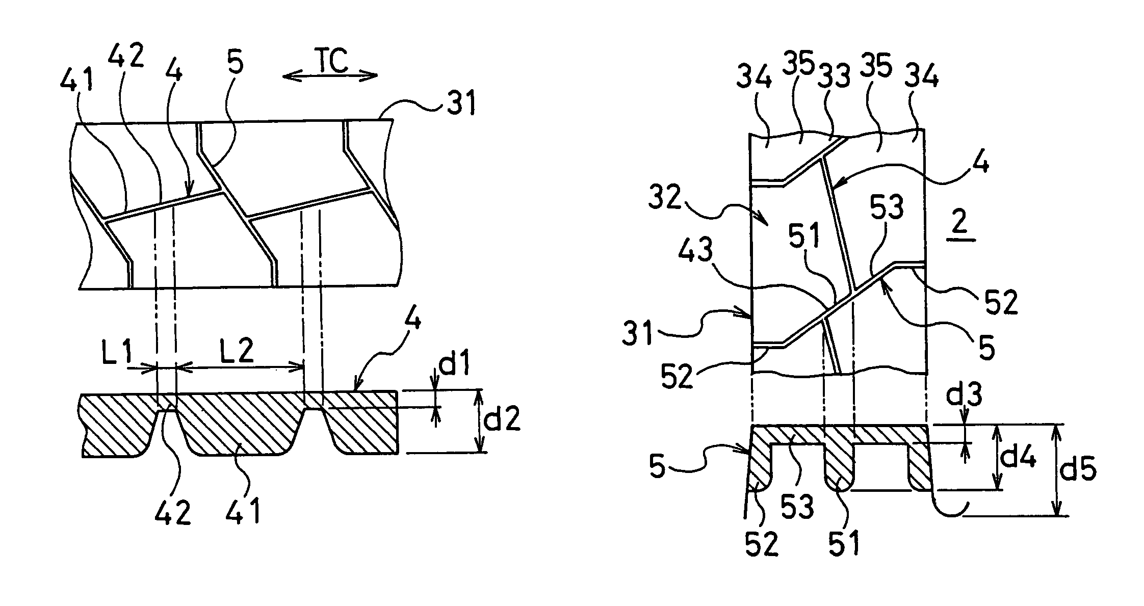
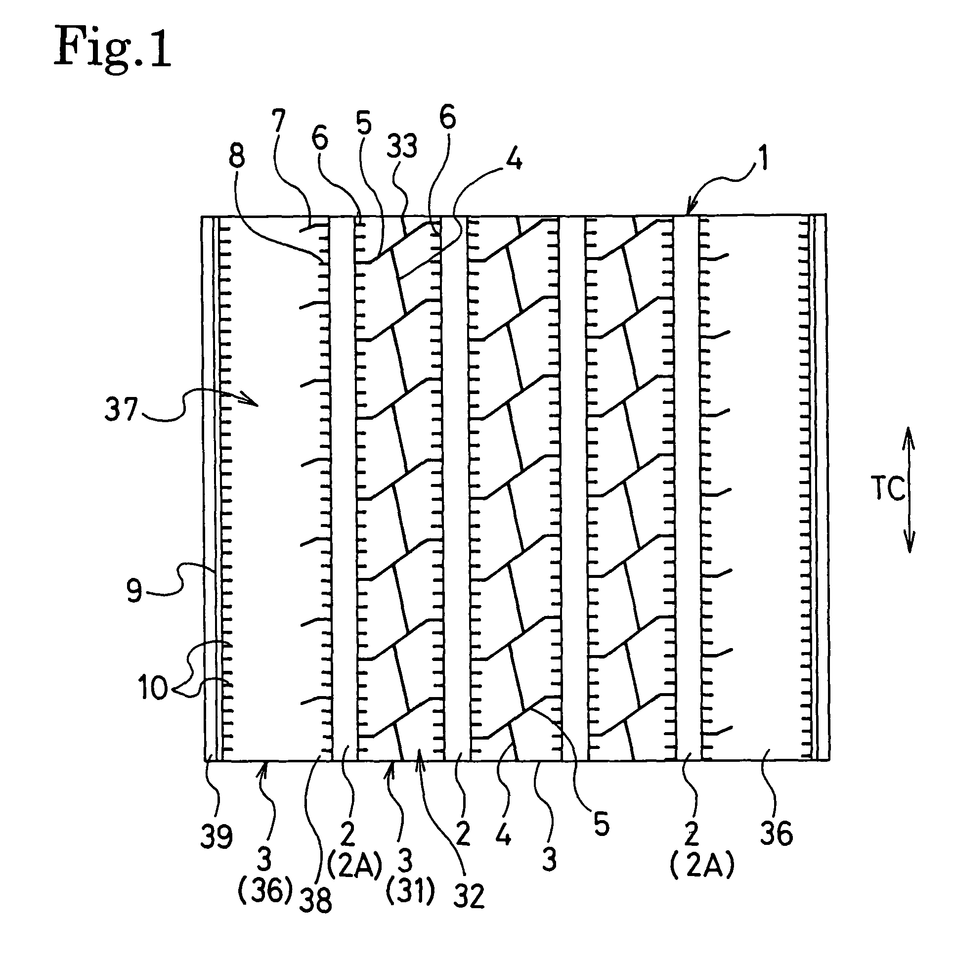
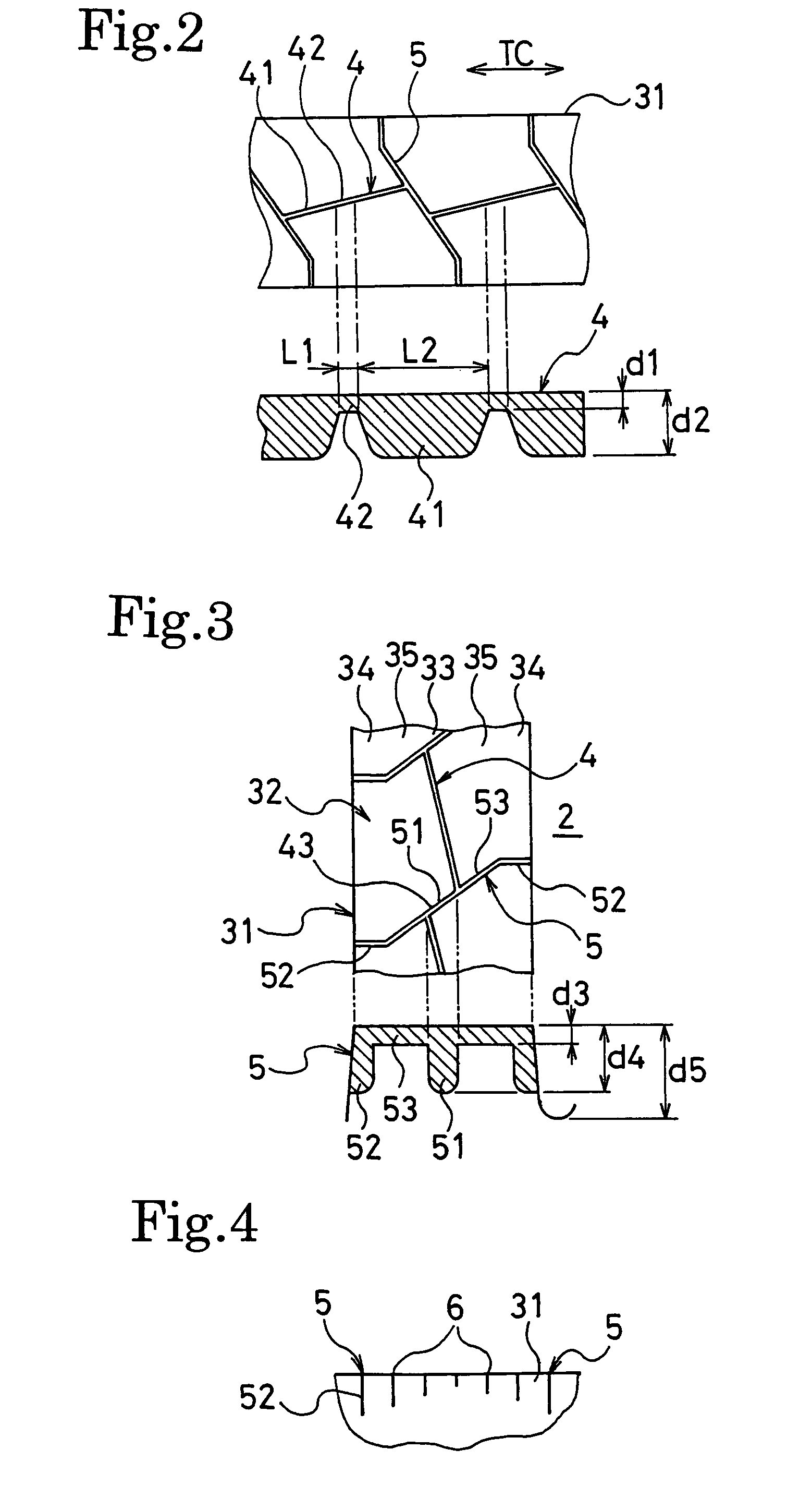
[0034]Prepared respectively were test tires according to the present invention tires 1 to 6, conventional tire, and comparison tires 1 and 2, each having a tire size of 11R22.5; the present invention tires 1 to 6 each have a rib pattern of FIG. 1 in which the ratio d1 / d2 of the depth d1 of the shallow sipe portions to the depth d2 of the deep sipe portions, the ratio L1 / L2 of the tire-circumferential length L1 of the shallow sipe portions to the tire-circumferential length L2 of the deep sipe portions, and the ratio d3 / d4 of the depth d3 of the widthwise sipe portions in the middle regions to the depth d4 of the widthwise sipe portions in the center and end regions are as shown in Table 1; the conventional tire has a tread pattern that is the same as the rib pattern of FIG. 1 except that no widthwise sipes are provided and the circumferential sipes do not extend consecutively but are arranged intermittently (the depth of the circumferential sipes are constant and the same as the dep...


PUM


Abstract

A circumferential sipe extends continuously in the circumferential direction of the tire in the center region of the tread surface section of a rib defined between circumferential grooves. Widthwise sipes are disposed at prescribed intervals in the circumferential direction of the tire in the tread surface section, the widthwise sipes extending in the widthwise direction of the tire in crossing relationship to the circumferential sipe, the widthwise sipes each having opposing terminal ends open to the circumferential grooves. The circumferential sipe changes in depth periodically in such a manner that the circumferential sipe is shallow between adjacent widthwise sipes. The widthwise sipes changes in depth in such a manner that they are greater in depth in the center region and end regions of the tread surface section.

Description

BACKGROUND OF THE INVENTION[0001]The present invention relates to pneumatic tires, and more particularly, to a pneumatic tire which can improve uneven wear resistance and wet performance.[0002]In general, pneumatic tires including a tread surface having a rib pattern, used for heavy duty vehicles such as buses and trucks, receive greater traverse shear strain at the end portions of the ribs than at the center portion thereof when the tires are engaged with a ground. Therefore, the compression amount of the end portions of the ribs in the circumferential direction and widthwise direction of the tire increases, whereby the end portions of the ribs locally go up in ground contact pressure, resulting in that such uneven wear that the end portions of the ribs wear more rapidly is apt to occur. In particular, pneumatic tires having rib patterns, used for the steering-wheel tires of trucks and buses which mainly travel a long distance consecutively at a high speed, strongly have such tende...

Claims


Application Information

Patent Timeline
Patent Type & Authority Patents(United States)
IPC IPC(8): B60C11/04B60C11/12
CPCB60C11/0306B60C11/04B60C11/12B60C11/1263Y10S152/03Y10S152/901B60C2200/06
Inventor SUZUKI, TAKAYUKI
Owner THE YOKOHAMA RUBBER CO LTD
Why Eureka
Try Eureka