Cable support hook

Active Publication Date: 2010-11-23
HANDLER JORDAN
View PDF11 Cites 28 Cited by
  • Summary
  • Abstract
  • Description
  • Claims
  • Application Information

AI Technical Summary

Benefits of technology

[0019]As an additional feature of the hooks hereof, all rounded edges may be flared away from the cable carrying surface to avoid damage to the cable jackets. The edges of the hook, its slides and the rails are preferably rounded to eliminate edges or corners that

Problems solved by technology

There might be electrical interference between cable transmissi

Method used


Image

  • Cable support hook
  • Cable support hook
  • Cable support hook

Examples


Example

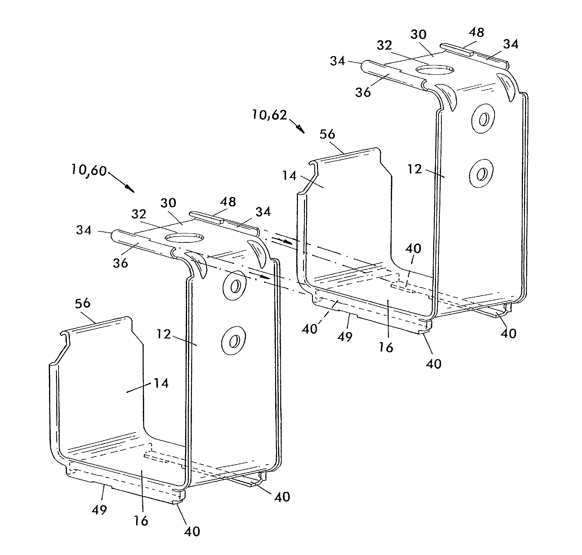
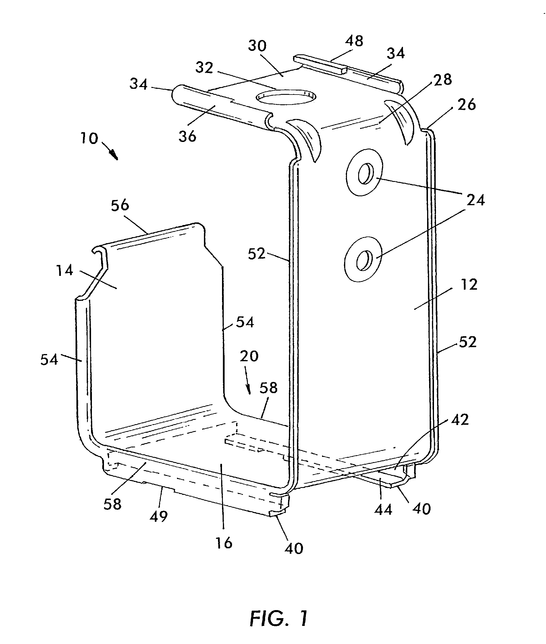
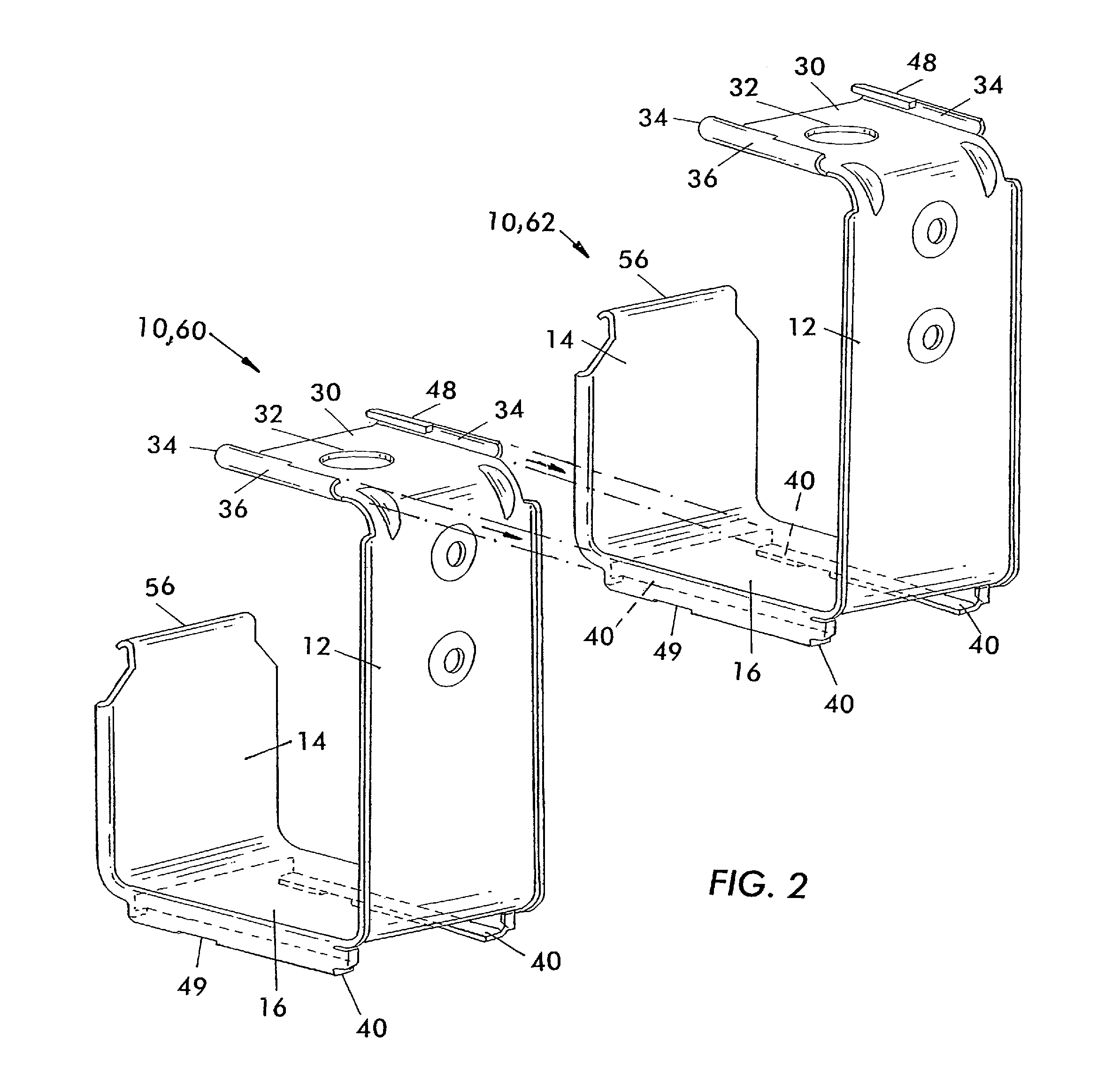
[0028]Referring to FIGS. 1 and 2, a preferred embodiment of a hook 10 includes a first rear, longer leg 12, a second front, shorter leg 14 spaced away from and parallel to the rear leg 12 and a bottom web 16 joining the front and rear legs 12 and 14. The hook 10 has an overall shape of a “J”. The legs 12, 14 and web 16 together define an open top notch 20 through which a plurality of cables 22 may be pulled and in which notch cable may be supported along a path in a manner known in the art.

[0029]The rear leg 12 is provided with openings 24 shaped, sized and positioned to receive conventional fasteners, not shown, such as bolts, screws, nails, etc., by which the hook may be fastened by its rear leg 12 to a support, such as a wall, not shown. This support provided to one hook may be sufficient for supporting a stack of the hooks, FIGS. 3 and 5, having features described herein.

[0030]At the top end 26 of the vertical rear leg 12, there is attached a forwardly directed, horizontal platf...


PUM


Abstract

A cable support hook of a general “J” shape with a rear leg, a front leg and a web joining the legs. A platform at the top of the rear leg extends parallel to the web. Slides at the top of the platform of a hook below may be received in rails at the bottom of the web of a hook above and the hook below is slid rearwardly along the guidance provided by the slides and the rails to stack the hook below beneath the hook above. No additional fastenings between the hooks are required.

Description

BACKGROUND OF THE INVENTION[0001]The present invention relates to a cable support hook for supporting cable passing the hook.[0002]Cable extends on a path along the outside of or inside a ceiling or wall in an enclosure, house or commercial or industrial building. The cable is typically used for supplying electrical energy, communication cables, data transmission cables, fiber optic cables, or the like. The cable is typically supported along its path.[0003]In one cable support configuration, a series of spaced apart cable support hooks support and define a path for the cable. The cable hooks are apart and generally close enough together along the path so that the cable is adequately supported. Each hook may be of a generally “J” shape, including a rear leg by which the hook is attached to some support, a usually shorter height front leg and a web joining the front and rear legs. The cable is supported in the notch at the web between the front and rear legs.[0004]Sometimes more than ...

Claims


Application Information

Patent Timeline
IPC IPC(8): E21F17/02
CPCF16L3/1058F16L3/1218F16L3/1233F16L3/133F16L3/222F16L3/23H02G3/30
Inventor HANDLER, JORDAN
Owner HANDLER JORDAN
Why Eureka
Try Eureka