Remote continuity and cable identifier and polarity checker system and method

a remote continuity and cable identification technology, applied in continuity testing, instruments, measurement devices, etc., can solve problems such as the inability of the technician to see or hear a continuity tester coupled to the near end

Active Publication Date: 2010-11-23
FLIR SYST INC
View PDF13 Cites 5 Cited by
  • Summary
  • Abstract
  • Description
  • Claims
  • Application Information

AI Technical Summary

Benefits of technology

[0006]This invention relates to a continuity test system that enables a user to identify and determine the polarity of conductive elements such as wires or cables (locally) out of a group of conductive elements, and to identify conductive elements such as wires or cables extending out to distant locations. This enables one person to identify and label the conductive elements under test with only one trip to the other end of the conductive elements.
[0007]The invention enables a person working alone to easily identify one or more conductive elements such as cables or wires out of two or more, and to find and label both ends of long distance runs.

Problems solved by technology

If these conductors are lengthy, when the technician is at the far end of the conductors, the technician may not be able to see or hear a continuity tester coupled to the near end.

Method used


Image

  • Remote continuity and cable identifier and polarity checker system and method
  • Remote continuity and cable identifier and polarity checker system and method
  • Remote continuity and cable identifier and polarity checker system and method

Examples


Embodiment Construction

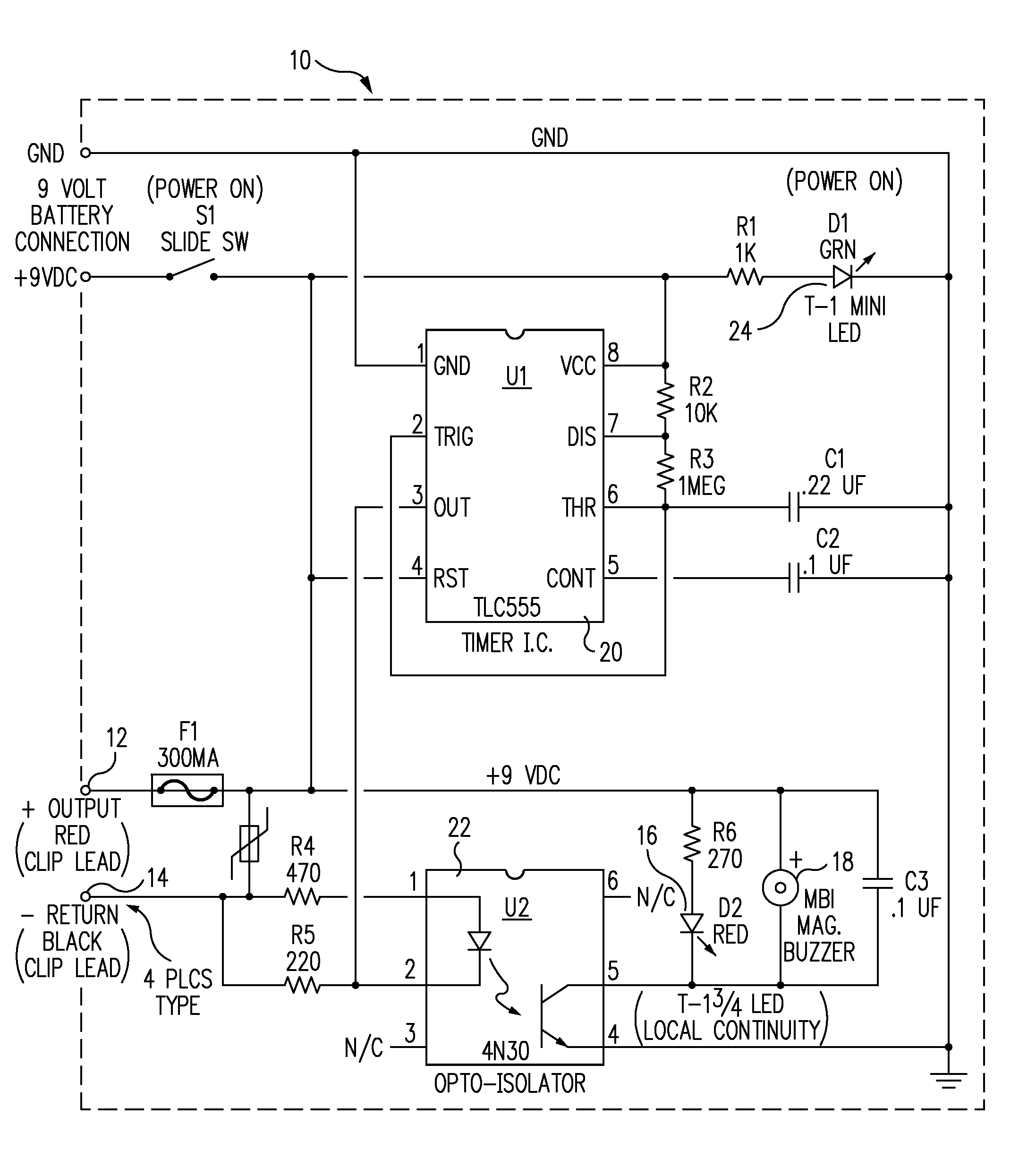
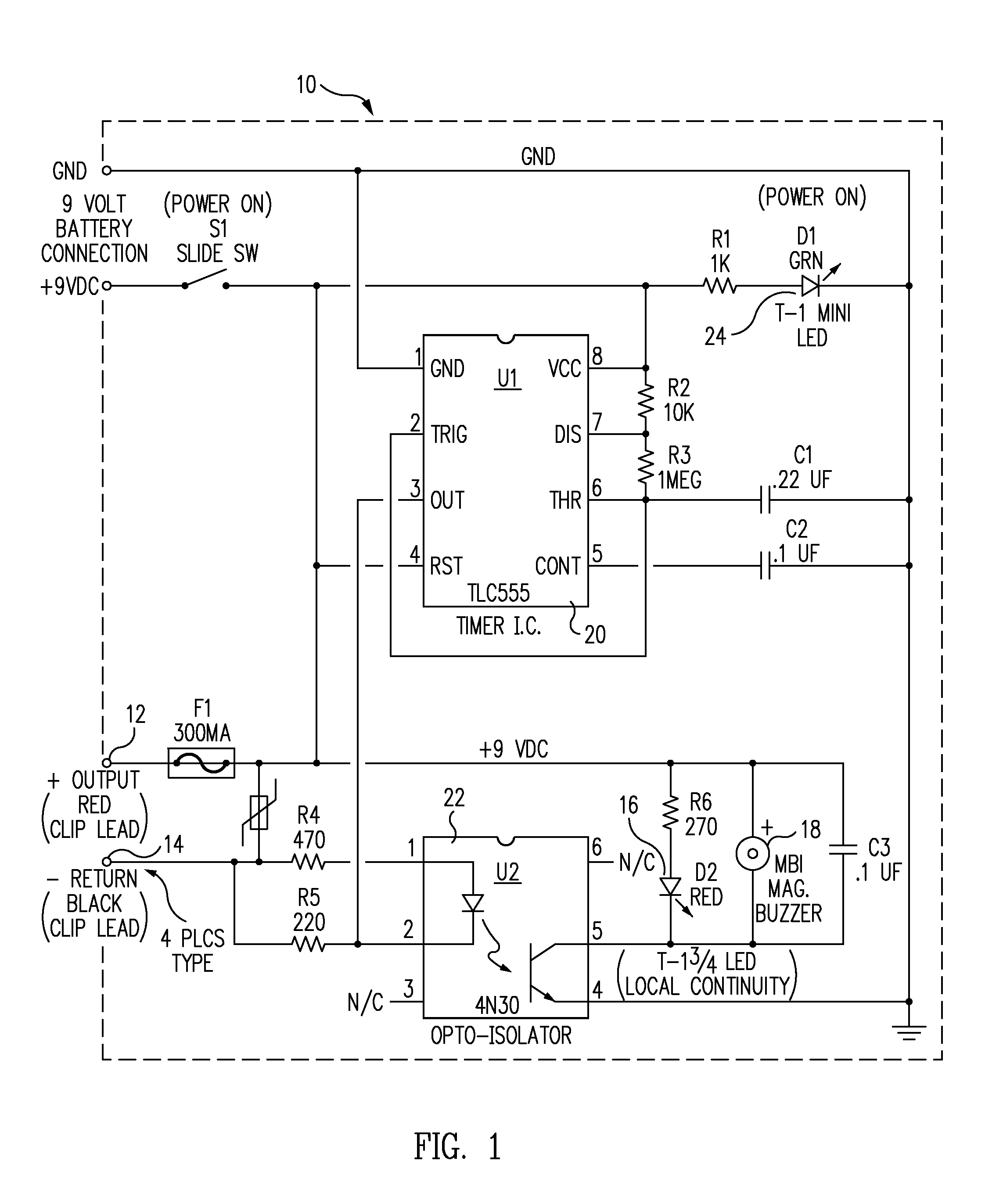
[0020]The preferred embodiment includes a two-lead tester 10, FIG. 1, that injects repetitive dc current pulses into one conductive test element (such as a wire or other conductor) to which it is connected, and then detects return pulses on a second conductive test element to which it is connected. See the FIG. 1 schematic, in which the various components are labeled with identifying values and other information known to those skilled in the art. Tester 10 has output 12 to which a lead is connected for connection to a wire or other conductor. The return lead is connected to input 14. Tester 10 is powered by a 9-volt battery, not shown. LED 24 indicates that the tester is on. Timer 20 provides a series of rapid current pulses to output 12. If these pulses return through input 14, the current flow through opto-isolator 22 causes red LED 16 to flash and buzzer or tone generator 18 to sound. This indicates continuity. It would be possible to have only one annunciator rather than the two...


PUM


Abstract

An electrical continuity test system with a tester and a remote probe. The tester includes circuitry for creating a pulsed current, an output for connection to a local end of a first test conductive element, to inject the pulses into the first test conductive element, an input for connection to a local end of a second test conductive element, and a visual and / or aural indication when the injected pulses are present on the second test conductive element. The remote probe includes an input for connection to a remote end of a first unidentified conductive element, an output for connection to a remote end of a second unidentified conductive element, a first visual and / or aural indication when the first unidentified conductive element is the first test conductive element, and a different visual and / or aural indication when the first unidentified conductive element is the second test conductive element.

Description

CROSS-REFERENCE TO RELATED APPLICATION[0001]This application claims priority of Provisional Application Ser. No. 60 / 825,437, filed Sep. 13, 2006, the entire contents of which are incorporated herein by reference.FIELD OF THE INVENTION[0002]This invention relates to an electrical system that determines both continuity and polarity.BACKGROUND OF THE INVENTION[0003]Continuity checking devices typically include a battery power source and a light and / or buzzer. When the device is coupled to a conductive path, electricity flows through the path, causing the light to light and the buzzer to sound. These devices work well when the user is close enough to see the light or hear the buzzer.[0004]There are situations in which a technician needs to identify both ends of one or more cables or sets of conductors among two or more such conductors. If these conductors are lengthy, when the technician is at the far end of the conductors, the technician may not be able to see or hear a continuity test...

Claims


Application Information

Patent Timeline
Patent Type & Authority Patents(United States)
IPC IPC(8): G01R19/00G01R31/08
CPCG01R31/023G01R31/026G01R31/60G01R31/54
Inventor BLANCHARD, JOSEPH
Owner FLIR SYST INC
Why Eureka
Try Eureka