Pressurized fluid coupler with anti-recoil feature and methods

a technology of pressure-coupling and feature, which is applied in the direction of couplings, valve arrangements, mechanical devices, etc., can solve the problem of bias in favor of component separation, and achieve the effect of minimizing the degree of unchecked pressure build-up

Active Publication Date: 2010-11-30
ENGINEERED CONTROLS INT
View PDF15 Cites 19 Cited by
  • Summary
  • Abstract
  • Description
  • Claims
  • Application Information

AI Technical Summary

Benefits of technology

[0006]The apparatus further comprises a pressure relief feature that permits the escape of pressurized fluid between the period of check valve disengagement and complete decoupling of the two components. As is known in the art, the component having the check valve will not undergo significant self-induced recoil, because the amount of pressurized fluid present between the check valve and the component's distal end is generally small. However, the non-checked component has a comparatively large reservoir of pressurized fluid, whose only means of escape is through that coupler's distal end. As a result, pressurized fluid escaping from the component orifice will result in an opposite force being applied to the component and any associated fluid delivery system(s). Moreover, fluid expelled from the non-checked component will impinge upon the other component, thereby inducing a pseudo-recoil force thereat. Depending upon the mode of implementation, the aforementioned pressure relief feature is intended to reduce the self-induced recoil force, the induced pseudo-recoil force, or both, as well as the Boyle recoil effect, which will be described in more detail below.
[0008]In many applications, the female component will be fluidly coupled to a source of pressurized fluid, which, for purposes of the instant example in this disclosure, is a gas. A check valve or equivalent structure is incorporated into the female component between the source of pressurized gas and a main orifice of the female component, thereby preventing escape of the pressurized gas from the source. Upon insertion of the male component, a suitable seal there between is created, the check valve is caused to open and the two components are mechanically engaged with each other. Subsequent to this, compressed gas enters the male component and is delivered according to system requirements. The decoupling process is similar but operates in reverse. However, as soon as the mechanical engagement between the two components is removed, there is a bias in favor of component separation. This bias, derived from Boyle's Law (an increase in pressure will cause a corresponding increase in volume, if possible), attempts to increase the volume defined by the component by separating the two components. Because the pressure relief feature exposes the volume to the environment, the pressure increase in the volume is rapidly countered by this bleeding of compressed gas.
[0010]The pressure relief feature beneficially addresses the Boyle recoil effect by minimizing the degree of unchecked pressure build-up between the two components after initial decoupling of the check valve. Moreover, a directed port, pressure relief feature associated with the component not possessing a check valve will address the Newton recoil effect by actively countering the component recoil resulting from pressurized fluid exiting the distal end.

Problems solved by technology

However, as soon as the mechanical engagement between the two components is removed, there is a bias in favor of component separation.

Method used


Image

  • Pressurized fluid coupler with anti-recoil feature and methods
  • Pressurized fluid coupler with anti-recoil feature and methods
  • Pressurized fluid coupler with anti-recoil feature and methods

Examples


Embodiment Construction

[0016]The following discussion is presented to enable a person skilled in the art to make and use the invention. Various modifications to the preferred embodiment will be readily apparent to those skilled in the art, and the generic principles herein may be applied to other embodiments and applications without departing from the spirit and scope of the present invention as defined by the appended claims. Thus, the present invention is not intended to be limited to the embodiment show[n], but is to be accorded the widest scope consistent with the principles and features disclosed herein.

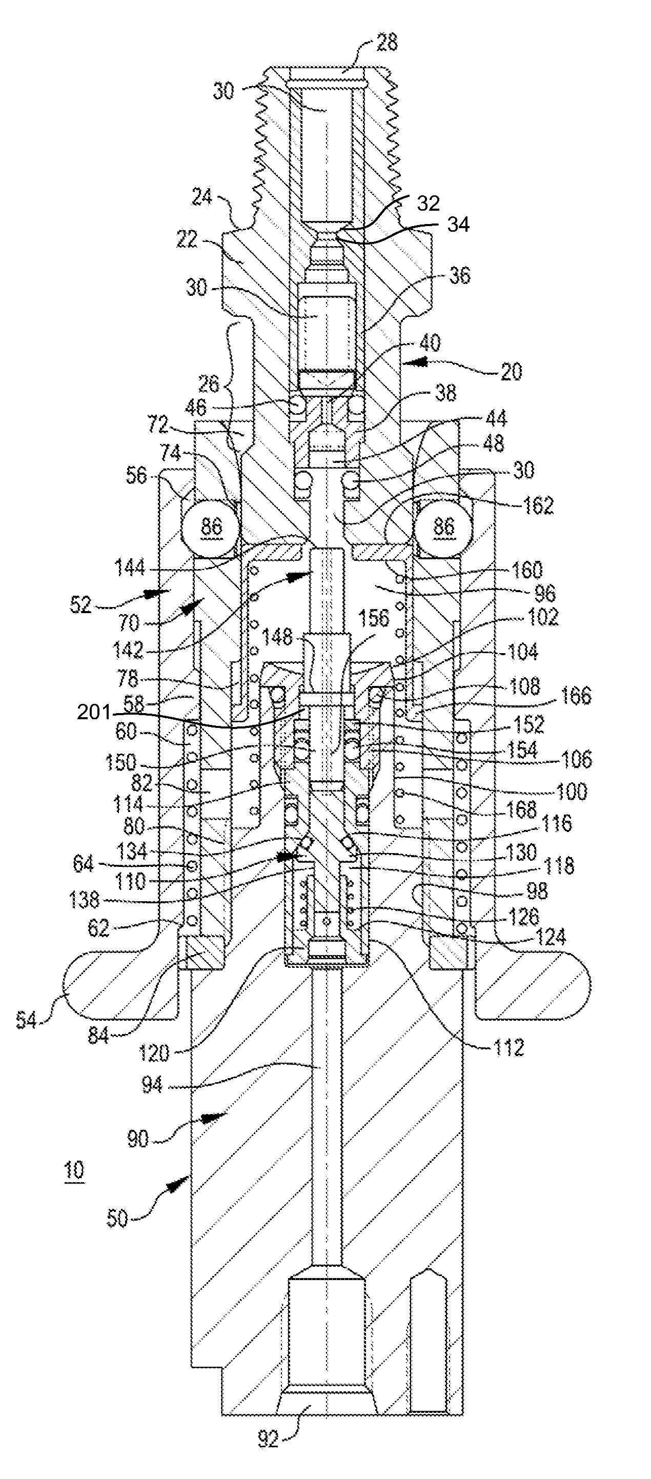
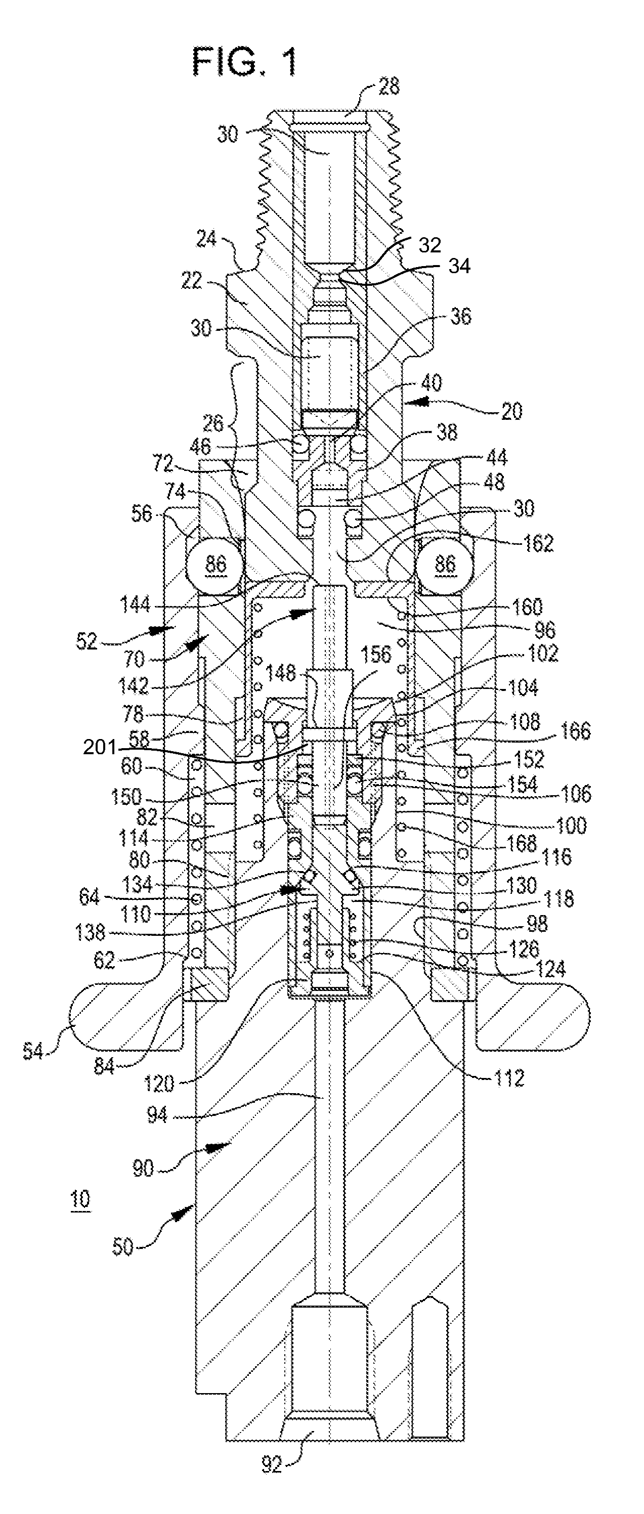
[0017]Turning then to the several Figures, wherein like numerals indicate like parts, and more particularly to Fig.1, coupler assembly 10 is shown in cross section for ease of viewing. Coupler assembly 10 comprises male fitting 20 and female fitting 50, which are intended to link to sources of high pressure fluid such as compressed gas, via threaded port 28 and threaded port 92, respectively. Unless o...


PUM


Abstract

The invention is directed to apparatus and methods for reducing recoil during uncoupling of pressurized couplers. The apparatus includes a male: a female component; and a check valve fluidly disposed between a proximal end and a distal end within one of the male component or female component. When the component including the check valve is pressurized, the check valve assumes a normally closed state. Upon coupling of the male component with the female component, the check valve is caused to open through the interaction of a probe linked to the check valve which contacts a portion of the opposing coupler, thereby opening the check valve and permitting pressurized fluid flow between the two components. At least one radially directed port fluidly couples the interface between the male and female couplers with the environment, which may be formed in one or both couplers.

Description

CROSS-REFERENCE To RELATED APPLICATION[0001]This is a utility application that claims benefit, under 35 USC §119(e), of U.S. provisional patent application No. 60 / 672,700, filed 18 Apr. 2005, which application is incorporated herein by reference.BACKGROUND OF THE INVENTION[0002]Conventional multi-component, pressurized couplers encounter a recoil effect when uncoupled, unless at least one pressurized line linked to the coupler is bled. In order to carry out such bleeding, additional structure such as shut-off valves and the like are usually needed. If at least one pressurized line is not bled prior to decoupling, then the pressurized gas or fluid is ejected from both coupler components. As required by Newton's second law, both coupler components will thereafter experience a recoil force (hereinafter a Newton recoil force), with the component having an unchecked reservoir of pressurized fluid being the most affected. In certain environments wherein high-pressure fluids are present, s...

Claims


Application Information

Patent Timeline
Patent Type & Authority Patents(United States)
IPC IPC(8): F16L37/28
CPCF16L37/23F16L37/40
Inventor KONISHI, M. HOWARDHUNCOVSKY, EDWIN
Owner ENGINEERED CONTROLS INT
Why Eureka
Try Eureka