Ladder caddy

Inactive Publication Date: 2010-12-07
BUTLER DAVID C +1
View PDF28 Cites 10 Cited by
  • Summary
  • Abstract
  • Description
  • Claims
  • Application Information

AI Technical Summary

Benefits of technology

[0007]The present invention provides an extremely versatile, easy to use, adjustable tool, paint, accessory and supply caddy for use on an extension ladder. The caddy of the invention can be used on ladders having rungs that are either round in cross section or have steps that are flat and more rectangular in shape providing a wider step surface. Both rungs and steps are usually referred to hereinafter simply as “rungs”. So as to accommodate either type of ladder rung or step, generally concave upper and lower mounting cradles attach to any consecutive rungs of an extension ladder at two separate attachments points. A quick release, spring loaded clamping mechanism allows the ladder caddy to be quickly and securely attached and then removed from a ladder by using the clamping mechanism to attach either down facing upper or lower mounting cradles to the rungs of the ladder. In the installed position, the distance between the upper and lower mounting cradles is made to be adjustable, due to differing extension ladder rung/step shapes as well as diameters and distances between rungs. The down facing concave surfaces of the upper and lower mounting cradles are held against the tops of consecutive ladder rungs and are in turn locked onto each rung using the quick release spring loaded clamping mechanism. The quick release spring loaded clamping mechanism is activated by pushing down, turning and releasing the clamping mechanism handle. In one position, the device is “locked” onto the ladder rung. By turning the clamping mechanism 180 degrees, the device is then in the unlocked position and can then be easily removed from the ladder. The upper facing concave surfaces of the cradles provide an area for the mounting of a removable winged tool bar or provide a resting area for other elongated tools, such as levels, framing squares, piping, molding, trim, conduit, etc. A removable winged bar, when attached, acts as a combination D-handled power/air tool holder, coiled cord holder, and retaining device for holding pipe, conduit, and other similar materials. The removable winged tool bar is attached into either of the up facing mounting cradles by using a secure clamping mechanism (without spring). The secure clamping mechanism is activated by tightening or untightening the secure clamping mechanism handle. The means for connecting the two concave mounting cradles together is provided by two vertical parallel pivoting bolts spaced several inches apart. The heads of the vertical parallel threaded bolts are recessed into the top facing surface of the upper mounting cradle. The vertical parallel pivoting bolts thread into a female threaded hole located on the raised bosses on the lower mounting cradle. Once adjustment has been made to a specific ladder, the bolts can be locked into p

Problems solved by technology

Being on a ladder creates a particular need to have many tools easily accessible, due to the difficulty of retrieving additional tools from a truck or other area at ground level, if necessary.
None of these devices, however, represents a completely satisfactory or highly versatile, adjustable solution to tool or material storage while working on an extension ladder.

Method used


Image

  • Ladder caddy
  • Ladder caddy
  • Ladder caddy

Examples


Embodiment Construction

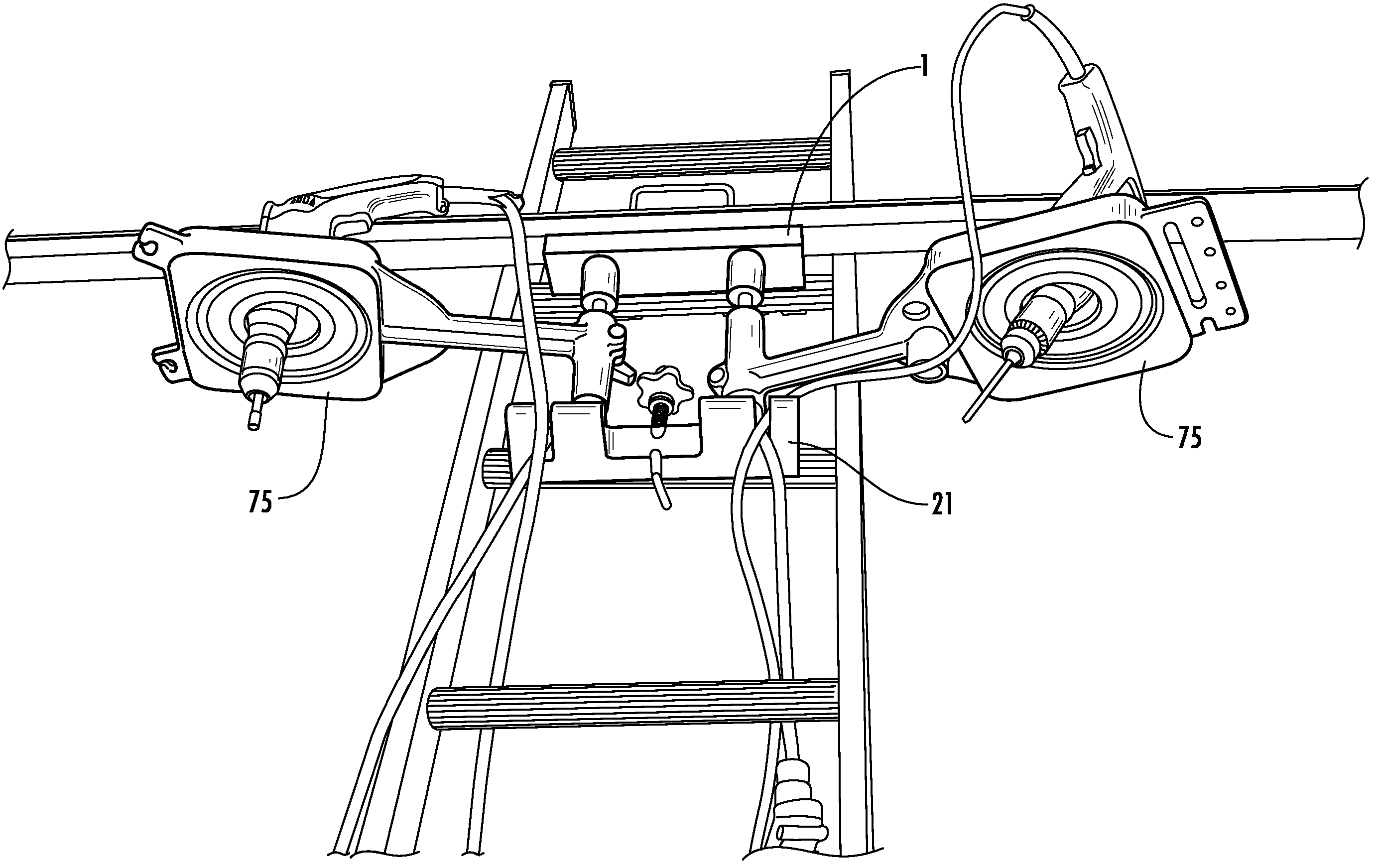
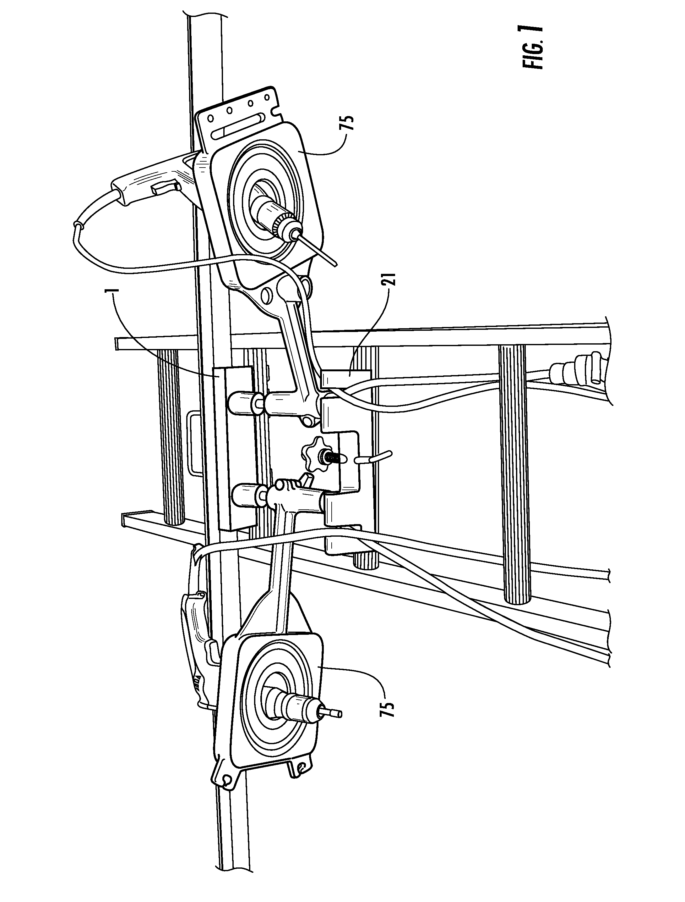
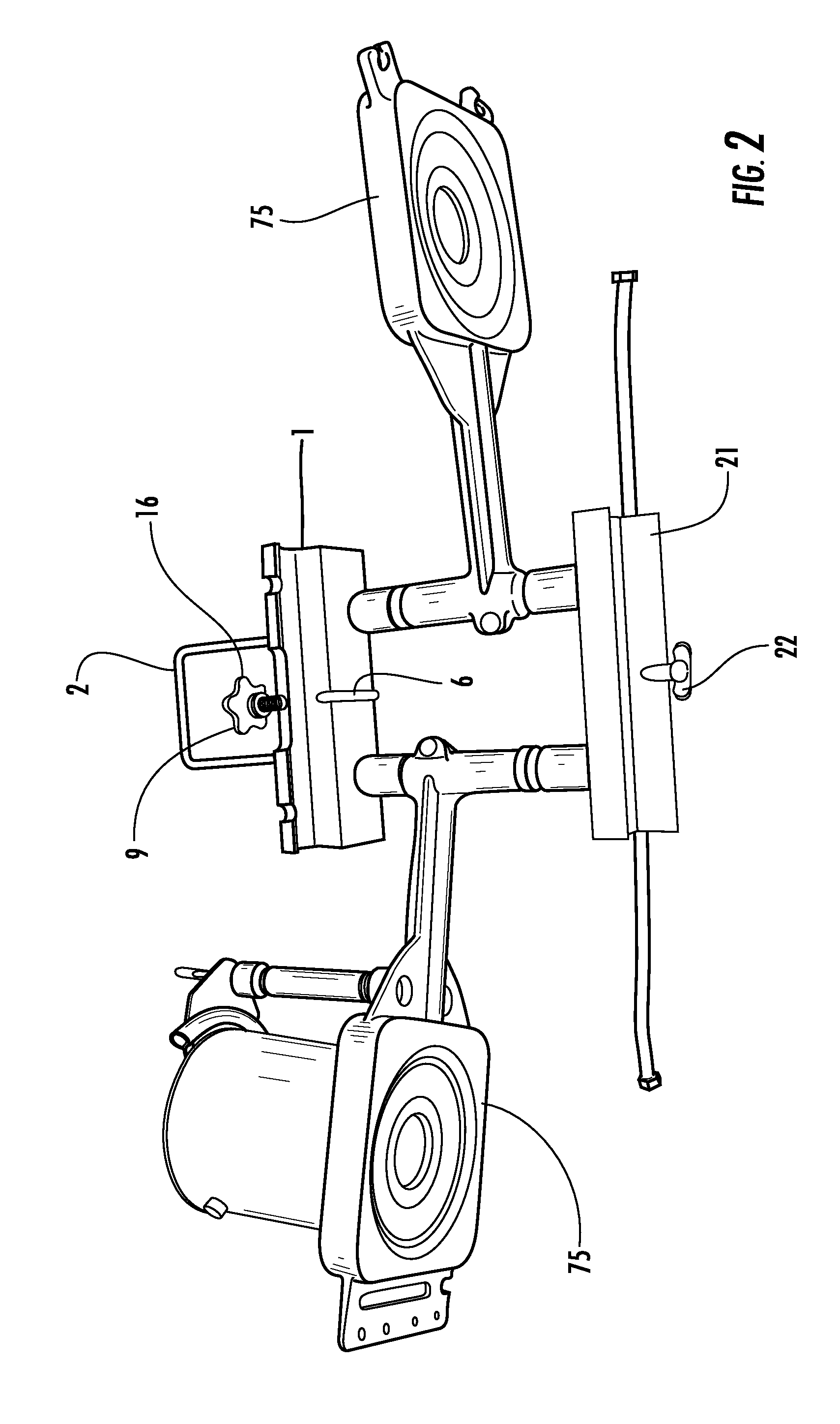
[0030]FIGS. 1-4 are views of one illustrative embodiment of the entire ladder caddy assembly of the invention with tool trays and a winged tool bar assembly included, and FIG. 1 shows the ladder caddy mounted on an extension ladder which, as is well known, has spaced apart rungs. The ladder caddy includes an upper mounting cradle assembly 1 and lower mounting cradle assembly 21. Upper mounting cradle 1 and lower mounting cradle 21 are spaced apart to accommodate the standard spacing between the rungs of a ladder, which spacing typically is approximately 12 inches. Thus, the spacing between the two mounting cradles 1 and 21 is adjustable, preferably between 11 and 13 inches, and more preferably 12 inches to adapt to different distances between ladder rungs as well as differences in ladder rung diameters or shapes. A concave mounting surface 26 (FIG. 9) on the lower side of the lower mounting cradle 21 rests on the upper half of the first ladder rung directly below the ladder rung whe...


PUM


Abstract

A versatile, easy to use, adjustable tool, paint, accessory and supply caddy for use on an extension ladder. The caddy can be used on ladders having rungs that are either round in cross section or have steps that are flat and more rectangular in shape. Upper and lower mounting cradles attach to any consecutive rungs of the extension ladder at two separate attachments points. A quick release, spring loaded clamping mechanism allows the ladder caddy to be quickly and securely attached and then removed from the ladder, with the upper and lower mounting cradles adjustable to accommodate different ladder rung / step shapes as well as diameters and distances between rungs. Paddle shaped trays can be locked in place on the caddy in a variety of positions, and the trays can swing over or under each other or be swung in opposing directions away from the ladder user thereby creating a useable work space adaptable to almost any ladder position.

Description

CROSS-REFERENCE TO RELATED APPLICATION[0001]The present application claims priority under 35 USC 119 to Provisional Application No. 60 / 807,898, filed Jul. 20, 2006, the entire contents of which application is hereby incorporated by reference.BACKGROUND OF THE INVENTION[0002]1. Field of the Invention[0003]This invention relates to the field of ladder accessories. More particularly, this invention relates to the field of an extension ladder or extended step ladder caddy for holding hand and power tools, painting supplies and similar supplies and equipment.[0004]2. Description of Related Art[0005]A workman at any job site often needs to have a significant number of tools and related equipment within easy reach. This is true whether the job site is at ground level, or is elevated off the ground such that the workman must perform the work while standing on a ladder. Being on a ladder creates a particular need to have many tools easily accessible, due to the difficulty of retrieving addit...

Claims


Application Information

Patent Timeline
IPC IPC(8): E06C5/32
CPCE06C7/14
Inventor BUTLER, DAVID C.DIXON, CLINT L.
Owner BUTLER DAVID C
Why Eureka
Try Eureka