Drill guide assembly for a bone fixation device

a bone fixation device and drill guide technology, applied in the field of drill guides, can solve the problems of small margin of error in spinal surgery, risk of tissue damage, misalignment of the screw within the plate hole, etc., and achieve the effect of quick and secure attachmen

Active Publication Date: 2005-02-03
SYNTHES USA
View PDF99 Cites 64 Cited by
  • Summary
  • Abstract
  • Description
  • Claims
  • Application Information

AI Technical Summary

Benefits of technology

[0008] According to one embodiment, there is provided a system and method for quickly and securely attaching a drill guide to a bone plate that resists rotational movement, requires minimal space within a surgical workspace, and provides tissue protection through an anterior spinal approach.

Problems solved by technology

The margin for error in spinal surgery is small, particularly because of the sensitivity of the spinal cord and the risk inherent with invasive procedures around the spinal cord.
Any misalignment of the screw within the plate hole risks tissue damage.
In addition, improperly seated screws may result in an unstable or insecure connection of the plate to the bony material, thus potentially defeating the usefulness of the plate.
One drawback of traditional drill guides is that the drill guides do not provide adequate soft tissue protection.
Thus, the surgeon must proceed with caution, requiring more time for the procedure and thus increasing the chance of complications for the patient under anesthesia.
Another drawback of conventional drill guides is that they do not engage the plate in a manner that prevents lateral or rotational movement of the plate with respect to the drill guide.

Method used


Image

  • Drill guide assembly for a bone fixation device
  • Drill guide assembly for a bone fixation device
  • Drill guide assembly for a bone fixation device

Examples


Embodiment Construction

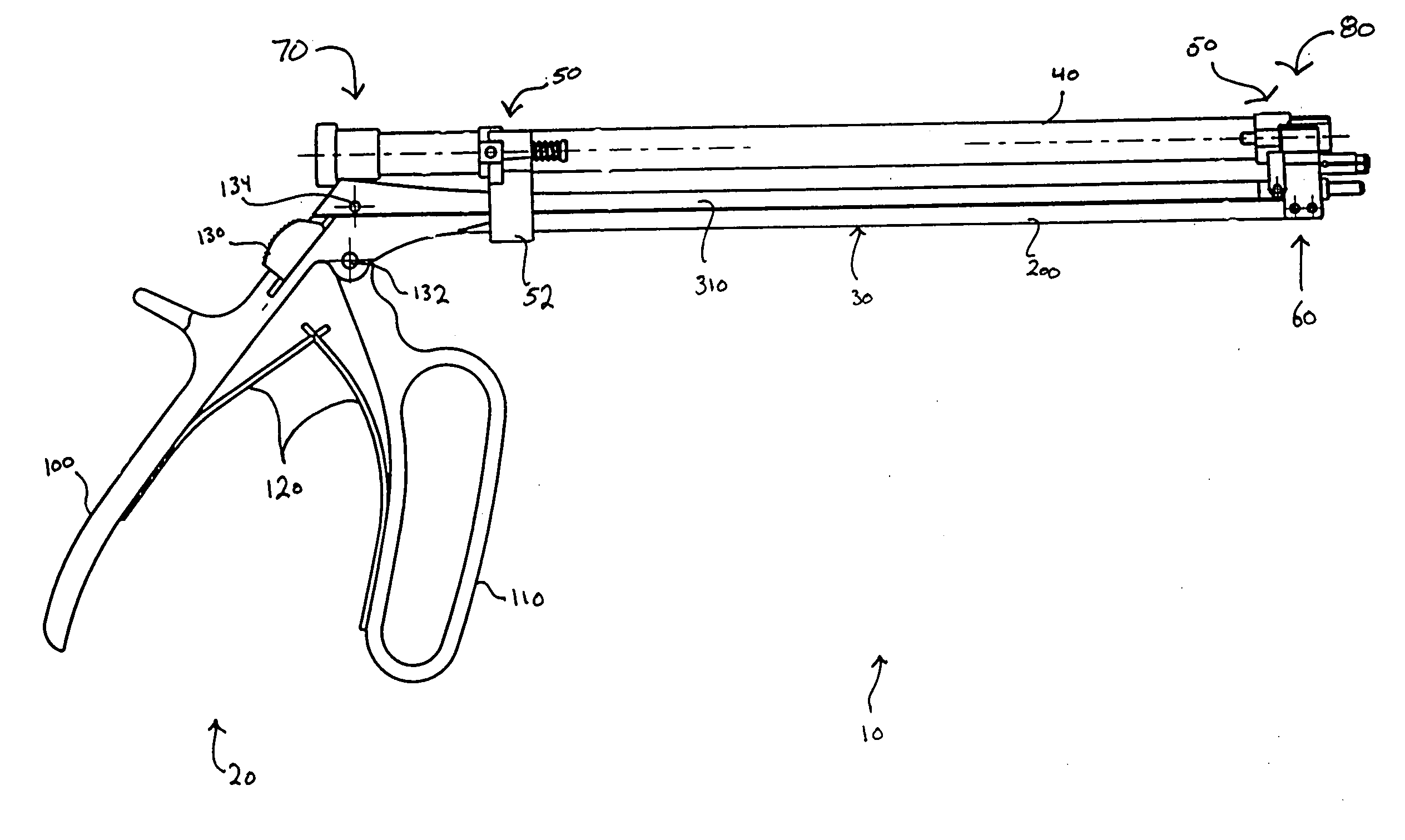
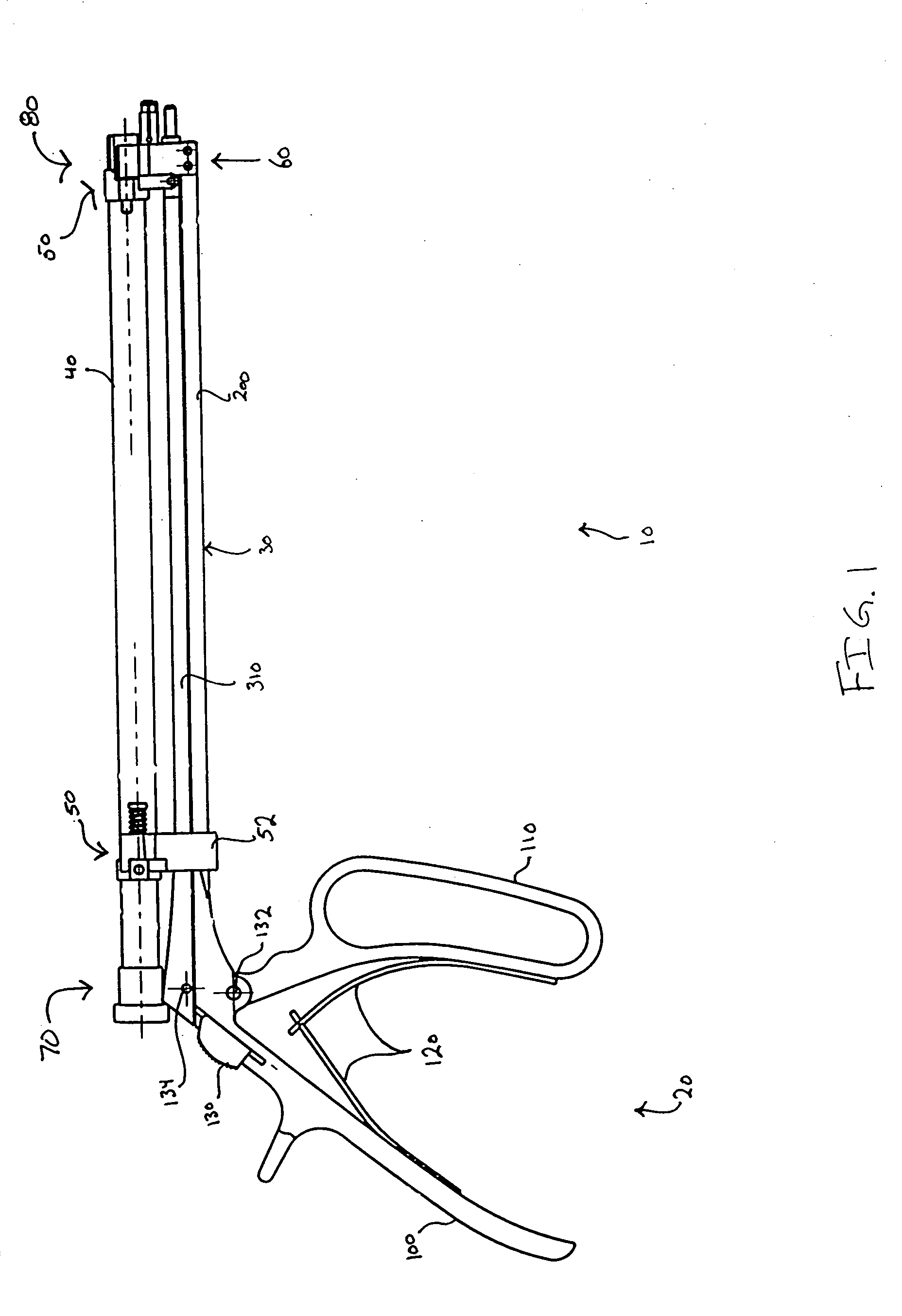
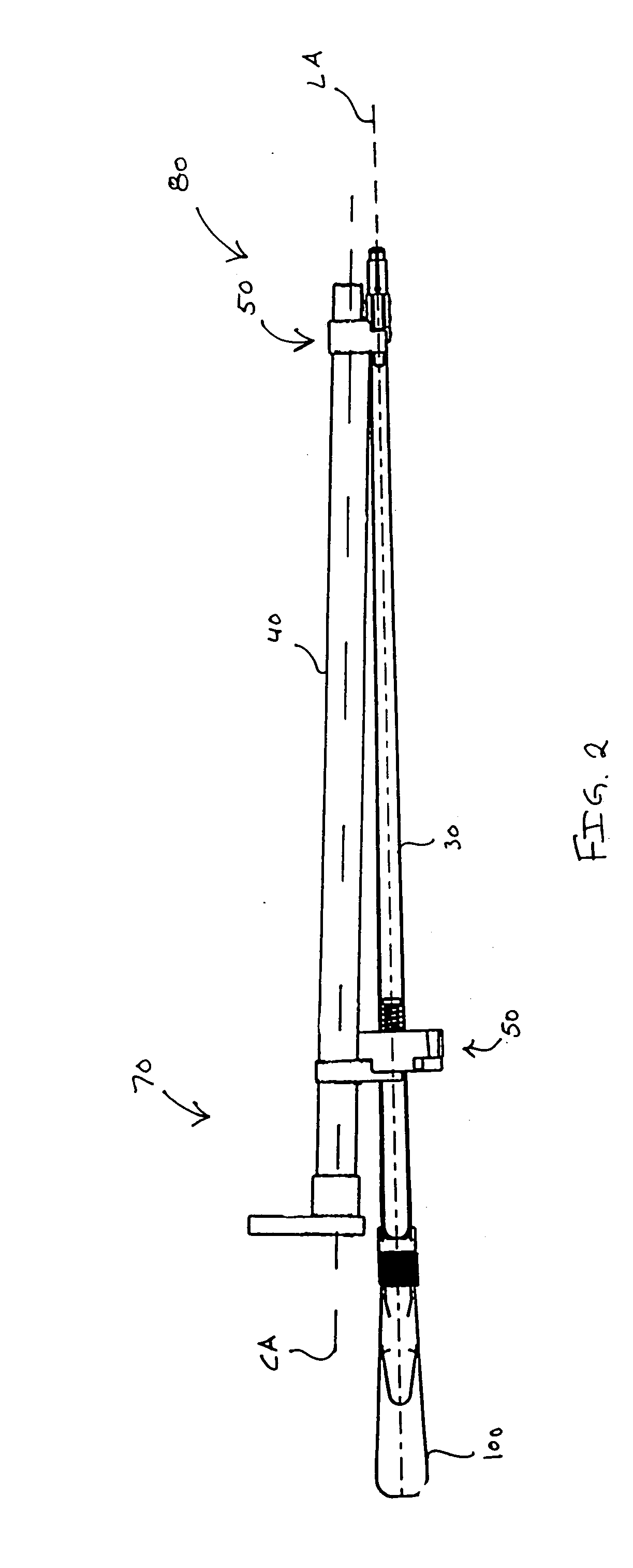
[0053] Referring to FIG. 1, there is shown an exemplary drill guide assembly 10, which is adapted for use with a spine fixation device, such as for example, a bone plate 500. While the drill guide assembly is disclosed in conjunction with a spinal plate it is contemplated that the drill guide assembly may be used in conjunction with bone plates used on any portion of the body. Drill guide assembly 10 generally includes an actuating handle 20, a body assembly 30, a guide barrel or barrels 40, a plate engaging and aligning mechanism 60, and optionally for the single barrel variety assembly, pivoting mechanisms 50. In general, to operate the drill guide assembly 10, a surgeon grasps the actuating handle 20 of the drill guide assembly 10. The surgeon then aligns the plate engaging and aligning mechanism 60 with a bone plate such that plate attachment mechanism 850 (FIG. 14) and locator pin 814 (FIG. 14) engage a slot 520, 510 (FIG. 19), respectively, in the bone plate. Once the plate at...


PUM


Abstract

A drill guide has a handle for holding and is configured to actuate a plate-engaging mechanism. An elongated member extends between proximal and distal portions with the proximal portion associated with the handle portion and the distal portion associated with the plate-engaging mechanism. The plate-engaging mechanism is actuated by an actuating member actuated by the second handle portion. The drill guide includes at least one guide sleeve rotatably coupled to the elongated member by a proximal and distal coupler. Furthermore, the plate-engaging mechanism includes a bone plate-engaging portion configured to couple with a bone plate when the second handle portion is moved in a first direction with respect to said first handle portion.

Description

CROSS-REFERENCE TO RELATED APPLICATIONS [0001] The present application claims priority under 35 U.S.C. § 119(e) to U.S. Provisional Application Ser. No. 60 / 491,898, filed Aug. 1, 2003, the disclosure of which is incorporated by reference herein in its entirety.FIELD OF THE INVENTION [0002] The present invention relates to a drill guide, such as for example, a surgical drill guide that is removably attachable to a fixation device, such as for example, a bone plate. More particularly, the surgical drill guide assembly provides soft tissue protection and precise alignment of at least one drill tube with bone screw holes of a bone plate, such as for example, a spinal bone plate. BACKGROUND OF THE INVENTION [0003] The use of surgical fixation plates for a variety of orthopedic applications is widely accepted. The plates are used by surgeons to stabilize, mend, or align a patient's bone as well as alter compression of patient's bones, and are typically fastened to the bones with a plurali...

Claims


Application Information

Patent Timeline
Patent Type & Authority Applications(United States)
IPC IPC(8): A61BA61B17/17
CPCA61B17/1757A61B17/1728A61B17/17
Inventor STIHL, PASCAL
Owner SYNTHES USA
Why Eureka
Try Eureka