Tissue separating and localizing catheter assembly
What is AI technical title?
AI technical title is built by Patsnap AI team. It summarizes the technical point description of the patent document.
a catheter and tissue technology, applied in the field of tissue separation and localization of catheters, can solve the problems of not being able to achieve the effect of removing cancerous tissue in less invasive ways, not yet being perfected, and not being able to achieve sufficient improvemen
Active Publication Date: 2010-12-07
ARTEMIS MEDICAL
View PDF78 Cites 273 Cited by
Summary
Abstract
Description
Claims
Application Information
AI Technical Summary
This helps you quickly interpret patents by identifying the three key elements:
Problems solved by technology
Method used
Benefits of technology
Benefits of technology
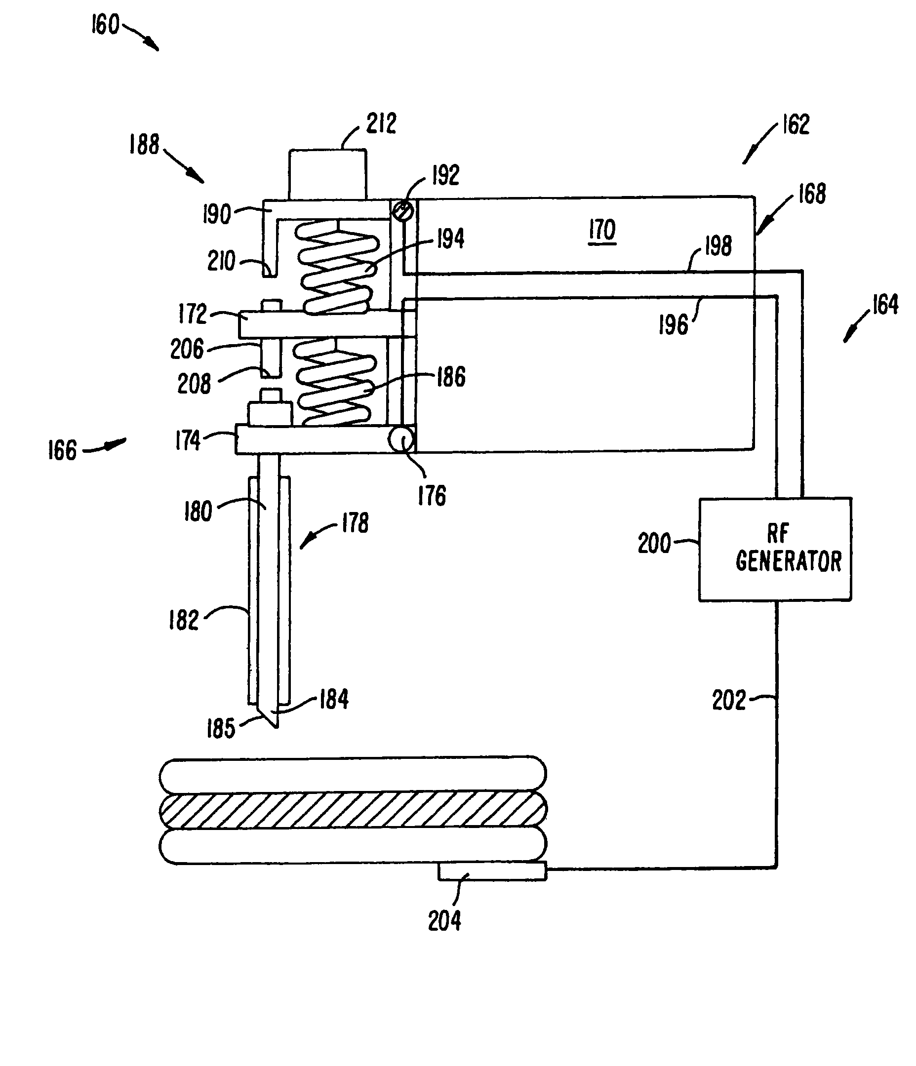
[0008]A first aspect of the invention is directed to a tissue-separating catheter assembly comprising a rotatable shaft having a distal shaft portion, a tissue separator device extending along the shaft and having an expandable distal separator part at the distal shaft portion, a radially-expandable localization device at the distal shaft portion, and an expandable tubular element movable so its outer end may be generally axially aligned with the localization device. A tissue section separated from surrounding tissue by the tissue separator device may be capturable by the localization device and the tubular element to aid removal of the separated tissue section from a patient.
Problems solved by technology
Open, excisional, surgical removal is often extremely invasive so that efforts to remove cancerous tissue in less invasive ways continue, but have not yet been perfected.
There is a variety of techniques that attempt to accomplish less invasive cancer therapy, but so far without sufficiently improved results.
However, conventional techniques, in contrast with Minimally Invasive Surgery (MIS) techniques, require a large core (that is more than about 15 mm diameter) incision.
Apparently these percutaneous systems damage “normal” tissue cells so that it is difficult to determine if the cells are “normal damaged” cells or early pre-cancerous (e.g. Atypical Ductal Hyerplasia (ADH)) cells.
Ollila et al. from the University of North Carolina, Chapel Hill, demonstrated that histology and pathology is compromised using these conventional techniques because of the damage done to the removed tissue specimens.
Method used
Image
Click on the blue label to locate the original text in one second.
Reading with bidirectional positioning of images and text.
Examples
Embodiment Construction
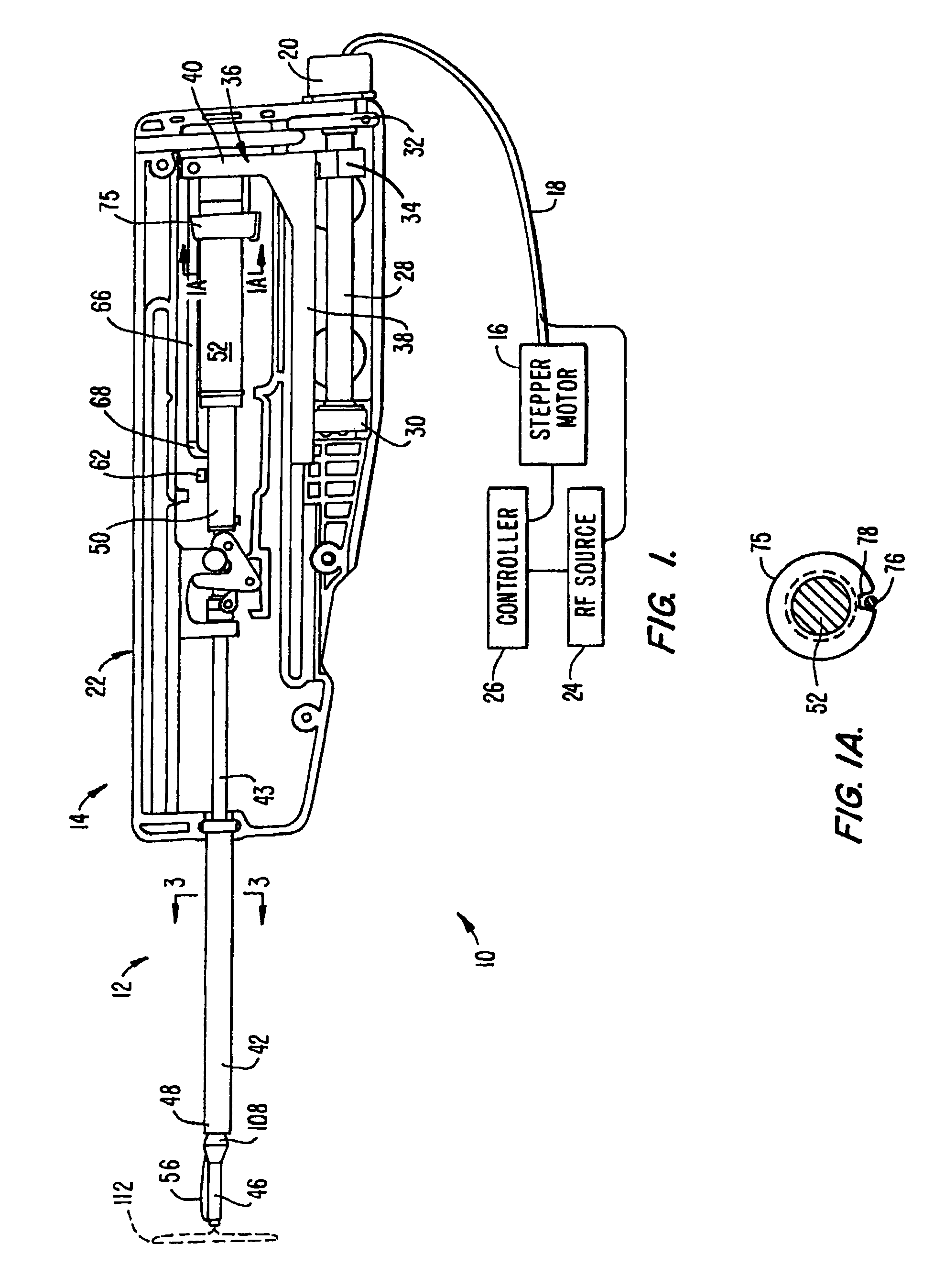
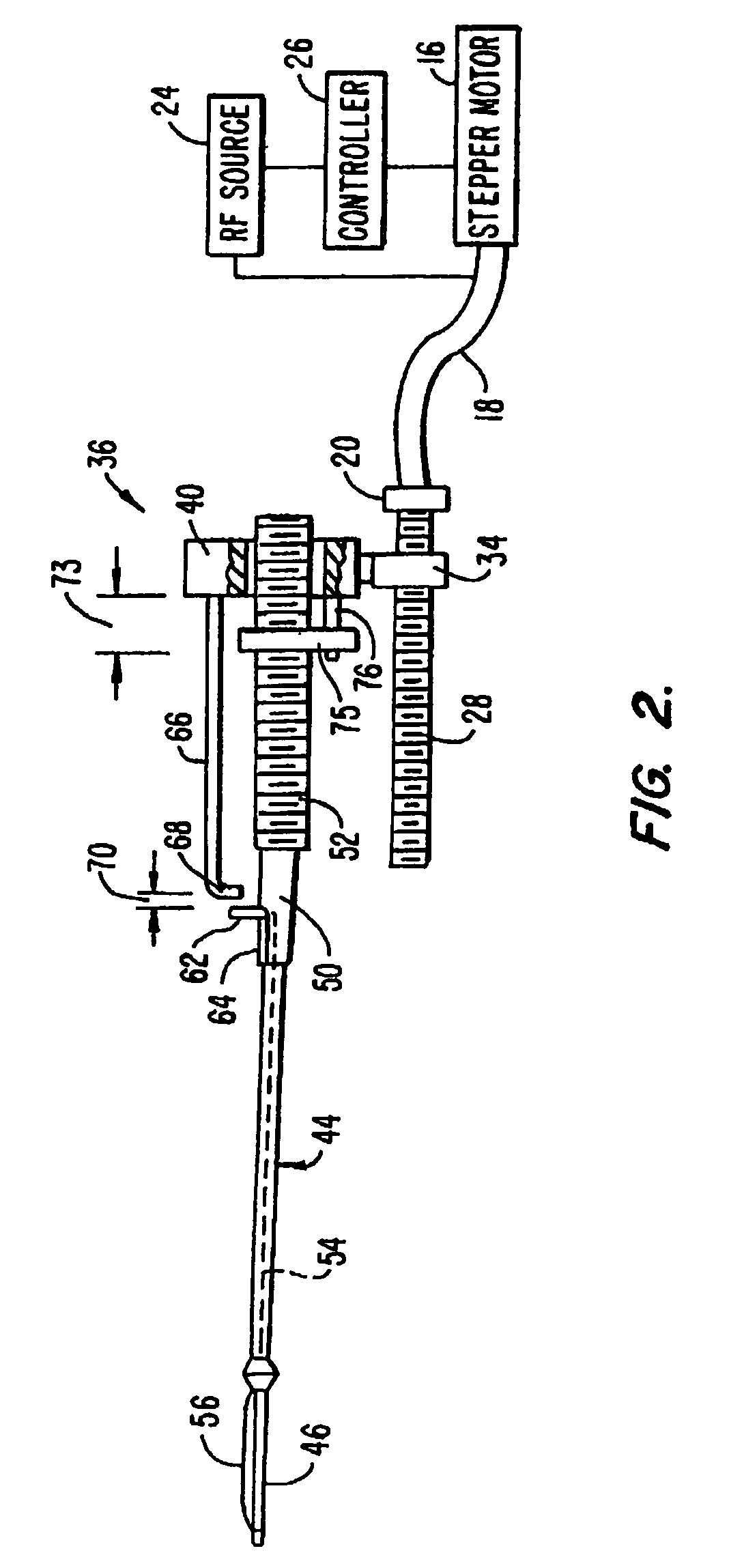
[0055]FIGS. 1 and 2 illustrate a tissue separator assembly 10 used to separate target tissue from surrounding tissue, typically within a patient's breast. The removal of target tissue may be for diagnostic or therapeutic purposes. The assembly 10 includes a catheter assembly 12 extending from a handle 14. Introduction of catheter assembly 12 into the patient, typically through the skin, is preferably aided by the use of, for example, a trocar or an RF tip to provide a suitable path through the tissue. A stepper motor 16 is connected to handle 14 by a drive cable 18 and a drive cable connector 20 mounted to the handle housing 22. Note that in the Figs. only one-half of handle housing 22 is shown; the other housing half is substantially similar. RF energy is supplied to catheter assembly 12 from an RF source 24, along drive cable 18 and to the interior of handle 14. A controller 26 controls the operation of stepper motor 16 as well as RF source 24, such as speed of operation and energ...
PUM
Abstract
A tissue-separating catheter assembly comprises a rotatable shaft, having a distal shaft portion, and a tissue separator device extending along the shaft. The tissue separator device has a distal separator part at the distal shaft portion movable between a retracted state, towards the distal shaft portion, and an outwardly extending, operational state, away from the distal shaft portion. A localization device is movable to a radially expanded state. An expandable tubular element is movable so that its outer end is generally axially aligned with the localization device so to capture a separated tissue section therebetween to aid removal of the separated tissue section from the patient.
Description
CROSS REFERENCE TO OTHER APPLICATIONS[0001]This application is a continuation of U.S. patent application Ser. No. 10 / 374,584, filed Feb. 25, 2003 now abandoned, which is a continuation-in-part of U.S. patent application Ser. No. 10 / 045,657, filed 7 Nov. 2001 now abandoned and entitled Tissue Separator Assembly And Method, which claims the benefit of U.S. Application Ser. No. 60 / 246,413, filed Nov. 7, 2000, all of which are hereby expressly incorporated by reference in their entirety for all purposes.[0002]This application is related to the following two patent applications: U.S. patent application Ser. No. 10 / 374,582, “Tissue Separating Catheter Assembly And Method,”; and U.S. patent application Ser. No. 10 / 374,583, now U.S. Pat. No. 6,994,677, “Tissue Localizing And Separating Assembly,”. See also: (1) U.S. Pat. No. 6,179,860 issued 30 Jan. 2001 and entitled Target Tissue Localization Device And Method, (2) International Publication No. WO 00 / 10471 published 2 Mar. 2000 and entitle...
Claims
Application Information
Patent Timeline
Application Date:The date an application was filed.
Publication Date:The date a patent or application was officially published.
First Publication Date:The earliest publication date of a patent with the same application number.
Issue Date:Publication date of the patent grant document.
PCT Entry Date:The Entry date of PCT National Phase.
Estimated Expiry Date:The statutory expiry date of a patent right according to the Patent Law, and it is the longest term of protection that the patent right can achieve without the termination of the patent right due to other reasons(Term extension factor has been taken into account ).
Invalid Date:Actual expiry date is based on effective date or publication date of legal transaction data of invalid patent.

