Vertical stent cutting process

a cutting process and vertical stent technology, applied in the field of vertical stent cutting process, can solve the problems of melting dross on the inside edge of the cut tube, aggravate the problem of ridding debris from the tube, and the tube may tend to bow

Inactive Publication Date: 2011-10-25
BOSTON SCI SCIMED INC
View PDF31 Cites 51 Cited by
  • Summary
  • Abstract
  • Description
  • Claims
  • Application Information

AI Technical Summary

Benefits of technology

[0016]The present invention is directed to a variety of embodiments. In at least one embodiment the invention is directed to a system for cutting, etching and / or otherwise processing a hollow metal tube for manufacturing a stent, wherein the tube / stent is positioned with its longitudinal axis in a vertical orientation relative to the ground. Such vertical orientation allows gravity to help maintain at least the free end the tube / stent in a stable position through out the cutting process.
[0018]Vertical orientation of the tube also encourages dross and other debris formed during cutting to be gravitationally drawn out of and away from the tube continuously through out the laser cutting process.
[0019]In some embodiments a stream of fluid or other media may be poured or injected through the lumen of the tube to cool the tube, provide increased stability to the tube, and / or assist in removing debris from the tube.
[0021]In some embodiments the flow of fluid or other media through the tube lumen will help protect the tube interior from potential damage caused by the cutting laser by disrupting the water jet and laser energy transmitted therethrough. Such use of a media flow in conjunction with a laser / water jet hybrid system is described in greater detail in a co-pending patent application filed simultaneously herewith entitled Tubular Cutting Process and System.
[0022]In some embodiments a collar or guide defines a chamber which at least a portion of the free end of the tube is inserted. The guide may be utilized to stabilize and / or minimize oscillations or other disruptive movement of the free end of the tube during the cutting process.
[0024]Where a fluid is sprayed or otherwise directed onto or through the tube, the fluid may be act as an oxidizer, cleaner, polishing agent, pretreatment or other solution. In some embodiments the fluid aids in removing debris from the tube during processing.

Problems solved by technology

The conventional laser cutting process typically results in the formation of melt dross on the inside edge of the cut tube.
The horizontal orientation of the tube additionally exacerbates the problem of ridding debris from the tube as debris must be actively driven out the open end of the tube.
Another more serious drawback is that in some cases, particularly in longer tubes, the tube may tend to bow as a result of gravity.
Such bowing may interfere with the precise nature of the stent cutting process, resulting in cutting errors or more significant damage to the tube / stent.
In addition, as the tube is rotated during cutting, any bowing of the tube will cause the unsecured end of the tube to oscillate resulting in excess strain being placed on the tube, and potentially leading to improper cutting and / or the formation of cutting imperfections.

Method used


Image

  • Vertical stent cutting process
  • Vertical stent cutting process
  • Vertical stent cutting process

Examples


Embodiment Construction

[0037]While this invention may be embodied in many different forms, there are described in detail herein specific preferred embodiments of the invention. This description is an exemplification of the principles of the invention and is not intended to limit the invention to the particular embodiments illustrated.

[0038]For the purposes of this disclosure, like reference numerals in the figures shall refer to like features unless otherwise indicated.

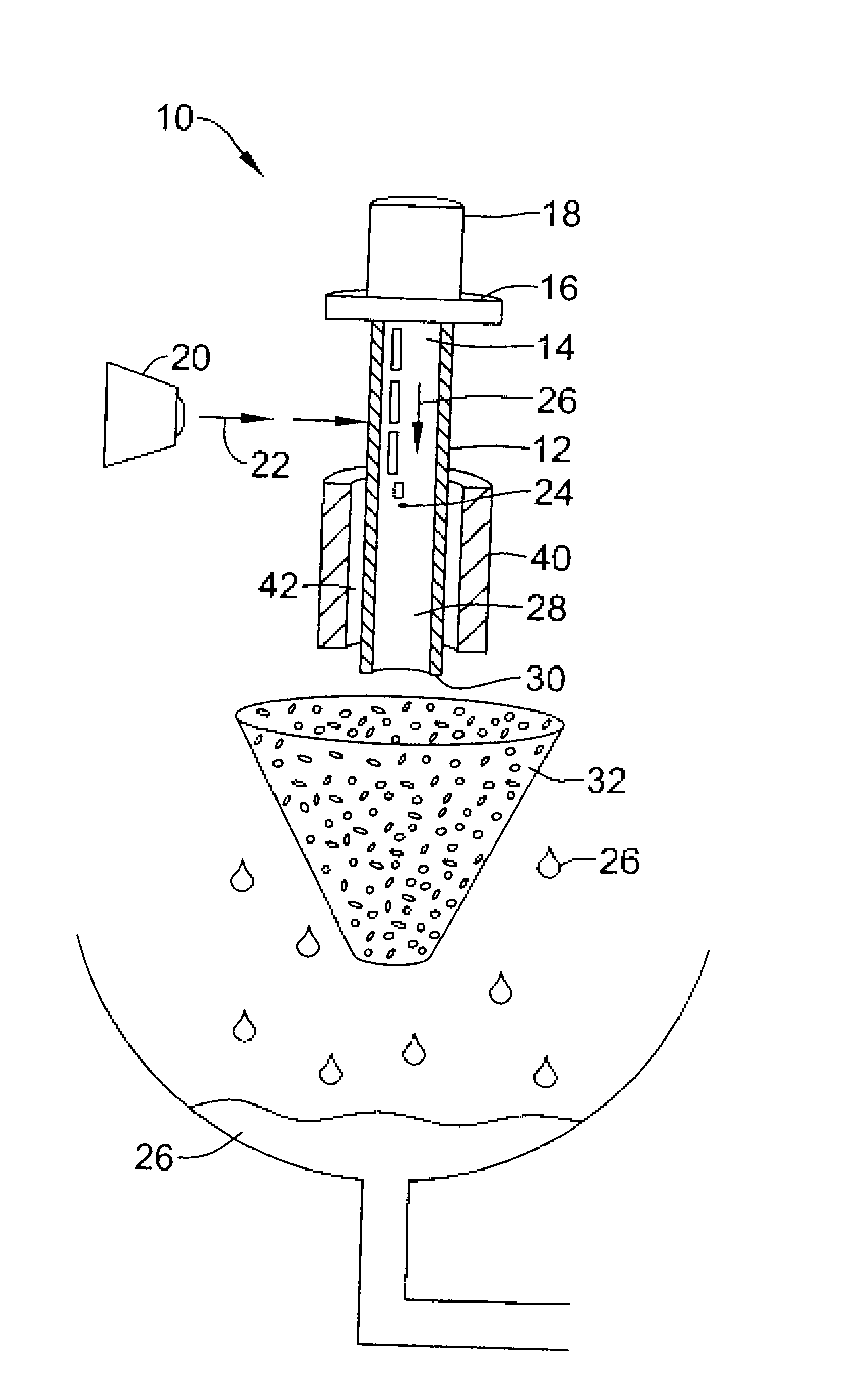
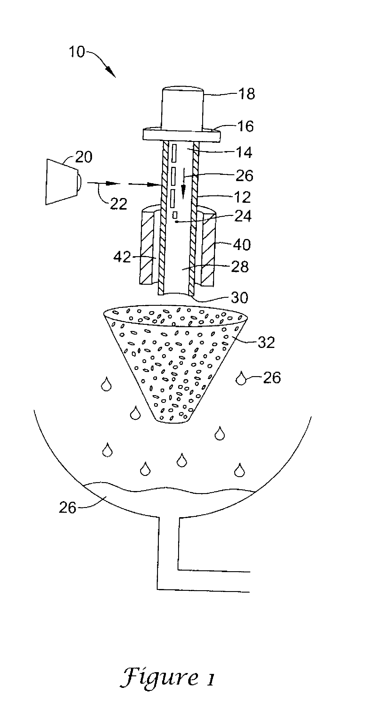
[0039]As indicated above the present invention is directed to a variety of embodiments. In at least one embodiment, shown in FIG. 1, the invention is directed to a mechanism (system), indicated generally at 10, for processing and / or cutting a hollow tubular body 12 into a medical device such as a stent.

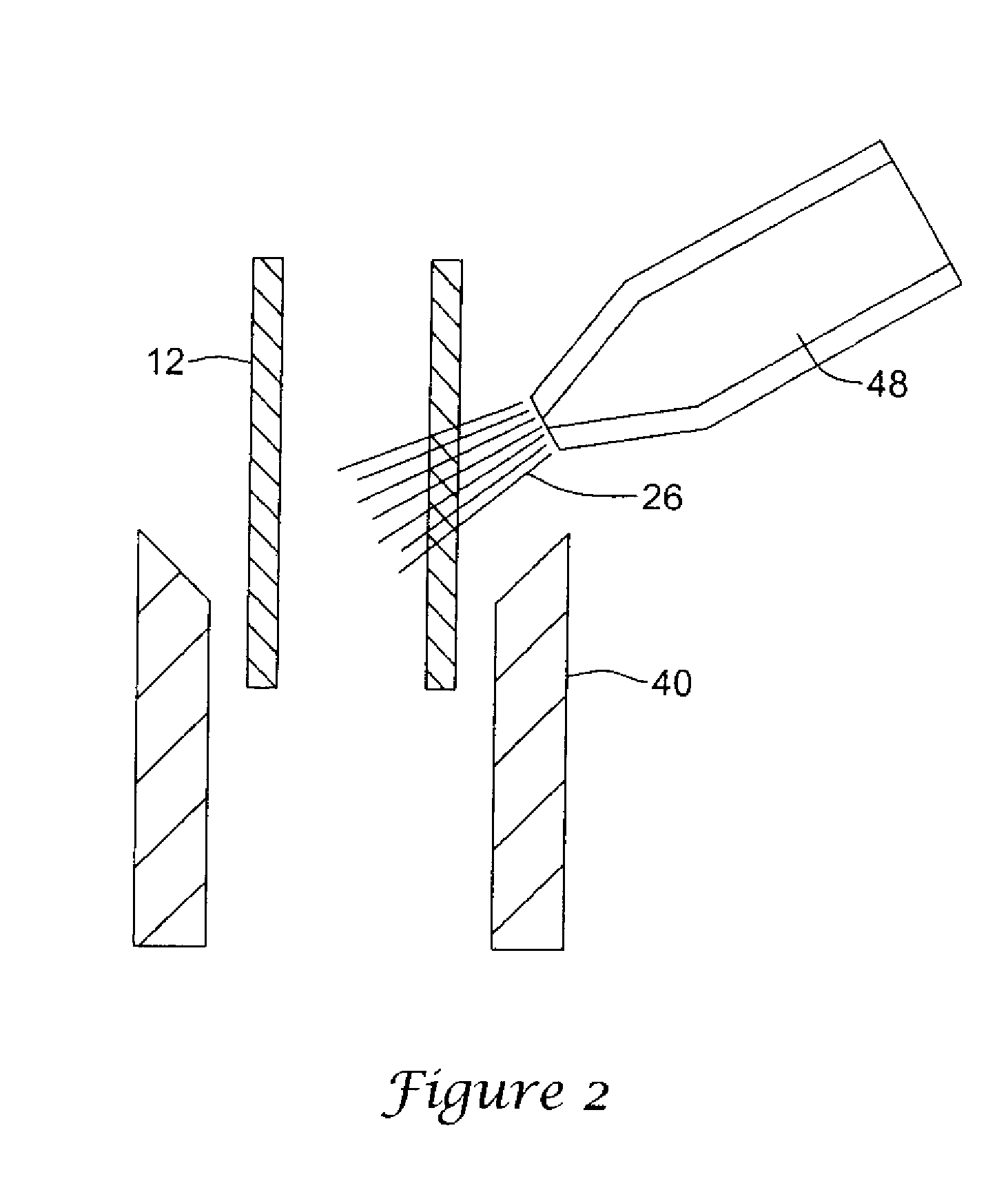
[0040]In the embodiment shown, the hollow tubular body 12 may be any type of tube suitable for laser processing and / or cutting. Such a tube 12 may be a tubular member suitable for the construction of a stent, graft, stent-graft, vena cava fil...


PUM

PropertyMeasurementUnit
energyaaaaaaaaaa
diameteraaaaaaaaaa
metallicaaaaaaaaaa

Abstract

A system and method for processing a tubular member for producing a medical device, wherein the tubular member is oriented in a longitudinally vertical position during processing.

Description

CROSS-REFERENCE TO RELATED APPLICATIONS[0001]This application is a continuation of U.S. application Ser. No. 10 / 190,975 filed Jul. 8, 2002.STATEMENT REGARDING FEDERALLY SPONSORED RESEARCH[0002]Not ApplicableBACKGROUND OF THE INVENTION[0003]A stent is a radially expandable endoprosthesis which is adapted to be implanted in a body lumen. Stents are typically used in the treatment of atherosclerotic stenosis in blood vessels and the like to reinforce body vessels and to prevent restenosis following angioplasty in the vascular system. They have also been implanted in urinary tracts, bile ducts and other bodily lumen. They may be self-expanding or expanded by an internal radial force, such as when mounted on a balloon.[0004]Delivery and implantation of a stent is accomplished by disposing the stent about a distal portion of the catheter, percutaneously inserting the distal portion of the catheter in a bodily vessel, advancing the catheter in the bodily lumen to a desired location, expand...

Claims


Application Information

Patent Timeline
Patent Type & Authority Patents(United States)
IPC IPC(8): B23K26/14A61F2/06A61F2/90B08B11/02B23K26/16B23K26/36B23K26/38B23K26/40
CPCB08B11/02B23K26/147B23K26/16B23K26/142B23K26/146B23K26/402B23K26/38A61F2/91B23K2203/42B23K2201/06B23K2101/06B23K2103/42B23K2103/50
Inventor MERDAN, KENNETH M.
Owner BOSTON SCI SCIMED INC
Why Eureka
Try Eureka