Hearing aid with a flexible shell

a flexible shell and hearing aid technology, applied in the field of hearing aids, can solve the problems of time-consuming manufacturing process, difficult to replace batteries, and relatively high cost of hearing aids,

Inactive Publication Date: 2005-03-08
HIMPP
View PDF11 Cites 47 Cited by
  • Summary
  • Abstract
  • Description
  • Claims
  • Application Information

AI Technical Summary

Benefits of technology

The tip can include a channel to aid in removal of wax from a bore in the tip. The tip includes a mushroom shaped portion and a sound bore attached to the mushroom shaped portion. The tip can include a first durometer material and a second durometer material, the first durometer material being relatively more compliant than the second durometer material. Preferably, the first durometer material forms the mushroom shaped portion of the tip and the second durometer material forms the sound bore of the tip.
will be apparent from the following more particular description of preferred embodiments of the invention, as illustrated in the accompanying drawings in which like reference characters refer to the same parts throughout the different views. The drawings are not necessarily to scale, emphasis instead being placed upon illustrating the principles of the invention.

Problems solved by technology

All of the above features including the structure, the method of making and the method of adjusting the hearing aid can make the hearing aid relatively expensive.
Conventionally, hearing aids have a battery that must be replaced periodically as the battery size is small and provides a limited lifetime of operation.
Hearing aid users frequently complain about the difficulty in replacing batteries.
Presently, the process of manufacturing hearing aids is time consuming and adds to the expense of the hearing aids.
These steps lengthen the process of forming a hearing aid.

Method used


Image

  • Hearing aid with a flexible shell
  • Hearing aid with a flexible shell
  • Hearing aid with a flexible shell

Examples


Embodiment Construction

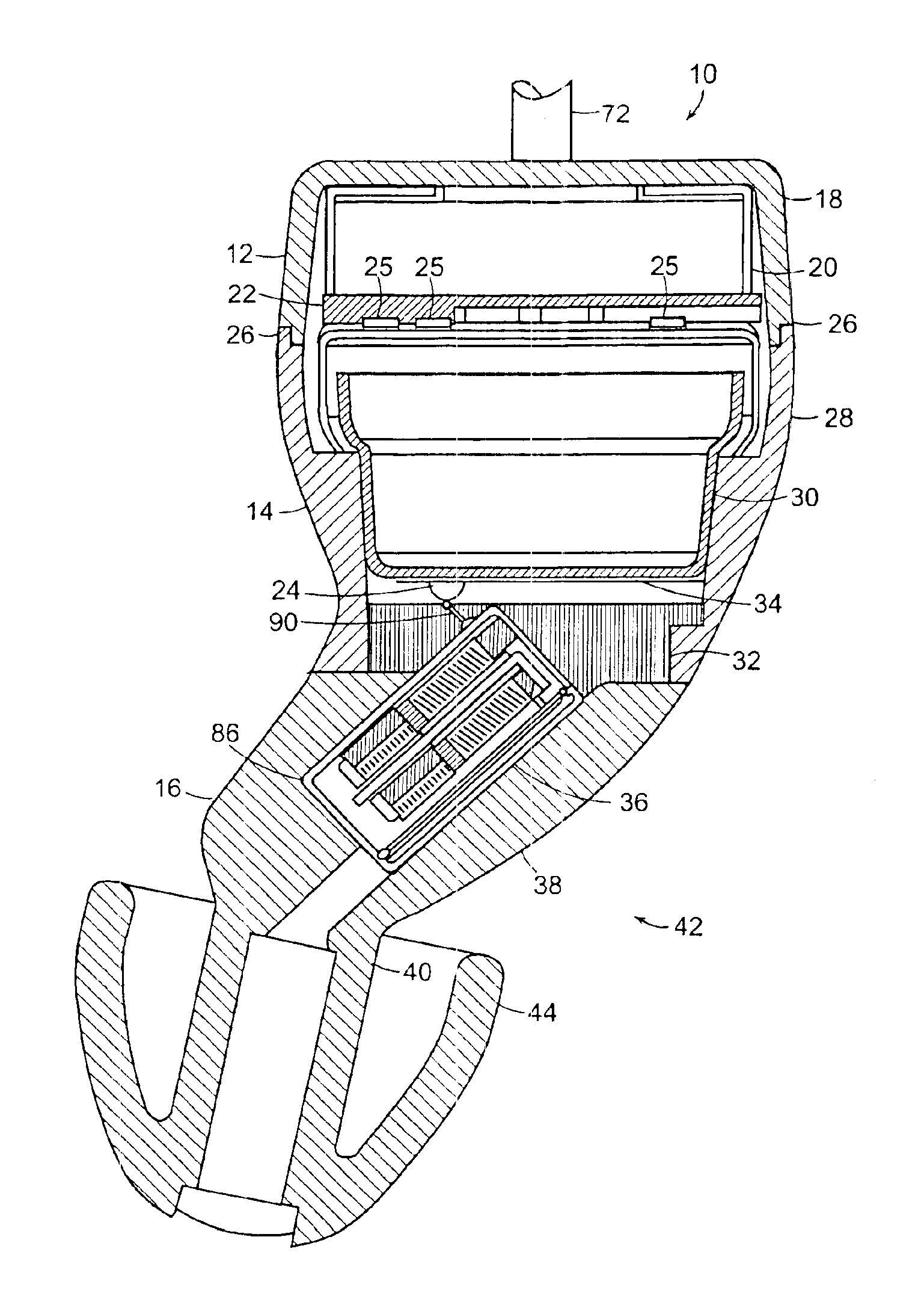
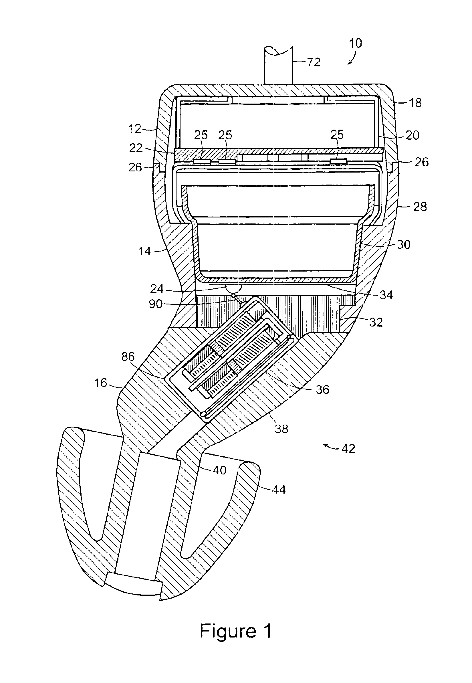
A hearing aid is shown in FIG. 1 and is given generally as 10. The hearing aid includes a first section 12, a second section 14 and a third section 16.

The first section 12 includes a cup or first section housing 18, a microphone 20, and electronics such as a microphone circuit board 22. The cup 18 can be a shell formed from a plastic material. The microphone 20 is secured within the cup 18 with a securing mechanism between the microphone 20 and cup 18. The securing mechanism can include a snap fit or a friction fit between the microphone 20 and cup 18. The microphone 20 and cup 18 can be provided as a complete subassembly. The microphone circuit board 22 includes a plurality of conductive protrusions 25 which interface electronically with the second section 14 of the hearing aid 10 and provide for an electrical connection between the microphone 20 and the second section 14. Preferably, the circuit board 22 includes three conductive protrusions 25. The conductive protrusions 25 can b...


PUM


Abstract

A hearing aid assembled from three sections includes a first section having a first housing containing a microphone and electronics, a second section having a second housing containing a battery a flex circuit mounted around the battery and a third section having a compliant tip and a receiver contained within a receptacle in the tip. The flex circuit provides solder less electrical connections among the electrical components of the hearing aid. The hearing aid also includes an actuator switch that allows the user to engage the hearing aid in an ON or an OFF mode of operation. Preferably, the actuator is electrically connected to the hearing aid without the use of solder. Connection between the first and second sections includes a mechanical securing mechanism, such as an interlocking joint.

Description

BACKGROUND OF THE INVENTIONModern hearing aids comprise an ear mold having therein the necessary electronics for amplifying and otherwise conditioning sound to compensate for a user's hearing loss. Such electronics generally include a microphone for receiving the sound and converting the sound to an electrical signal, an electronic circuit for amplifying and processing the signal produced by the microphone, a speaker, also known as a receiver, for converting the processed signals into sound energy and a battery for providing operational power to the hearing aid. The ear mold can be generally made of plastic, and is specially designed and molded to fill the ear of the person who is to use the hearing aid. Generally, the ear mold is made of a hard plastic so as to have a long life and so that it can be periodically cleaned. The electronics of the signal processing circuitry are typically adjusted to meet its users specific hearing requirements. These requirements are obtained by first...

Claims


Application Information

Patent Timeline
Patent Type & Authority Patents(United States)
IPC IPC(8): H04R25/02H04R25/00H05K1/18
CPCH04R25/608H04R25/65H04R25/656H04R25/456H04R25/602H04R25/604H05K1/189H04R25/654H04R2225/023H04R2225/61H04R25/652H04R25/603H04R25/609
Inventor LEEDOM, MARVIN A.
Owner HIMPP
Why Eureka
Try Eureka